

Sakshi Education

In most practical situations, there is a need for transmitting data in both directions. One way of achieving full duplex data transmission is to have two separate communication channels and use each one for simplex data traffic (in different directions). If this is done, we have two separate physical circuits, each with a ''forward'' channel (for data) and a ''reverse'' channel (for acknowledgements). In both cases, the bandwidth of the reverse channel is almost entirely wasted. In effect, the user is paying for two circuits but using only the capacity of one. A better idea is to use the same circuit for data in both directions. After all, in protocols 2 and 3 it was already being used to transmit frames both ways, and the reverse channel has the same capacity as the forward channel. In this model the data frames from A to B are intermixed with the acknowledgement frames from A to B. By looking at the kind field in the header of an incoming frame, the receiver can tell whether the frame is data or acknowledgement.
Although interleaving data and control frames on the same circuit is an improvement over having two separate physical circuits, yet another improvement is possible. When a data frame arrives, instead of immediately sending a separate control frame, the receiver restrains itself and waits until the network layer passes it the next packet. The acknowledgement is attached to the outgoing data frame (using the ack field in the frame header). In effect, the acknowledgement gets a free ride on the next outgoing data frame. The technique of temporarily delaying outgoing acknowledgements, so that they can be hooked onto the next outgoing data frame is known as piggybacking. The principal advantage of using piggybacking over having distinct acknowledgement frames is a better use of the available channel bandwidth. The ack field in the frame header costs only a few bits, whereas a separate frame would need a header, the acknowledgement, and a checksum. In addition, fewer frames sent mean fewer ''frame arrival'' interrupts, and perhaps fewer buffers in the receiver, depending on how the receiver's software is organized. In the next protocol to be examined, the piggyback field costs only 1 bit in the frame header. It rarely costs more than a few bits.
Although interleaving data and control frames on the same circuit is an improvement over having two separate physical circuits, yet another improvement is possible. When a data frame arrives, instead of immediately sending a separate control frame, the receiver restrains itself and waits until the network layer passes it the next packet. The acknowledgement is attached to the outgoing data frame (using the ack field in the frame header). In effect, the acknowledgement gets a free ride on the next outgoing data frame. The technique of temporarily delaying outgoing acknowledgements, so that they can be hooked onto the next outgoing data frame is known as piggybacking. The principal advantage of using piggybacking over having distinct acknowledgement frames is a better use of the available channel bandwidth. The ack field in the frame header costs only a few bits, whereas a separate frame would need a header, the acknowledgement, and a checksum. In addition, fewer frames sent mean fewer ''frame arrival'' interrupts, and perhaps fewer buffers in the receiver, depending on how the receiver's software is organized. In the next protocol to be examined, the piggyback field costs only 1 bit in the frame header. It rarely costs more than a few bits.
Fig.8.A sliding window of size 1, with a 3-bit sequence number (a) Initially (b) After the first frame has been sent (c) After the first frame has been received (d) After the first acknowledgement has been received.
Since frames currently within the sender's window may ultimately be lost or damaged in transit, the sender must keep all these frames in its memory for possible retransmission. Thus, if the maximum window size is n, the sender needs n buffers to hold the unacknowledged frames. If the window ever grows to its maximum size, the sending data link layer must forcibly shut off the network layer until another buffer becomes free. The receiving data link layer's window corresponds to the frames it may accept. Any frame falling outside the window is discarded without comment. When a frame whose sequence number is equal to the lower edge of the window is received, it is passed to the network layer, an acknowledgement is generated, and the window is rotated by one. Unlike the sender's window, the receiver's window always remains at its initial size. Note that a window size of 1 means that the data link layer only accepts frames in order, but for larger windows this is not so. The network layer, in contrast, is always fed data in the proper order, regardless of the data link layer's window size. Figure 8 shows an example with a maximum window size of 1. Initially, no frame are outstanding, so the lower and upper edges of the sender’s window are equal, but as time goes on, the situation progresses as shown.
4.1.1 A One-Bit Sliding Window Protocol:
Before tackling the general case, let us first examine a sliding window protocol with a maximum window size of 1. Such a protocol uses stop-and-wait since the sender transmits a frame and waits for its acknowledgement before sending the next one. Figure 9.1 depicts such a protocol. Like the others, it starts out by defining some variables. Next_frame_to_send tells which frame the sender is trying to send. Similarly, frame_expected tells which frame the receiver is expecting. In both cases, 0 and 1 are the only possibilities.
Under normal circumstances, one of the two data link layers goes first and transmits the first frame. In other words, only one of the data link layer programs should contain the to_physical_layer and start_timer procedure calls outside the main loop. In the event that both data link layers start off simultaneously, a peculiar situation arises, as discussed later. The starting machine fetches the first packet from its network layer, builds a frame from it, and sends it. When this (or any) frame arrives, the receiving data link layer checks to see if it is a duplicate, just as in protocol 3. If the frame is the one expected, it is passed to the network layer and the receiver's window is slid up. The acknowledgement field contains the number of the last frame received without error. If this number agrees with the sequence number of the frame the sender is trying to send, the sender knows it is done with the frame stored in buffer and can fetch the next packet from its network layer. If the sequence number disagrees, it must continue trying to send the same frame. Whenever a frame is received, a frame is also sent back. Now let us examine protocol 4 to see how resilient it is to pathological scenarios. Assume that computer A is trying to send its frame 0 to computer B and that B is trying to send its frame 0 to A. Suppose that A sends frame to B, but A's timeout interval is a little too short. Consequently, A may time out repeatedly, sending a series of identical frames, all with seq = 0 and ack = 1.
When the first valid frame arrives at computer B, it will be accepted and frame_expected will be set to 1. All the subsequent frames will be rejected because B is now expecting frames with sequence number 1, not 0. Furthermore, since all the duplicates have ack = 1 and B is still waiting for an acknowledgement of 0, B will not fetch a new packet from its network layer. After every rejected duplicate comes in, B sends A a frame containing seq = 0 and ack = 0. Eventually, one of these arrives correctly at A, causing A to begin sending the next packet. No combination of lost frames or premature timeouts can cause the protocol to deliver duplicate packets to either network layer, to skip a packet, or to deadlock.
However, a peculiar situation arises if both sides simultaneously send an initial packet. This synchronization difficulty is illustrated by Fig.9.2. In part (a), the normal operation of the protocol is shown. In (b) the peculiarity is illustrated. If B waits for A's first frame before sending one of its own, the sequence is as shown in (a), and every frame is accepted. However, if A and B simultaneously initiate communication, their first frames cross, and the data link layers then get into situation (b). In (a) each frame arrival brings a new packet for the network layer; there are no duplicates. In (b) half of the frames contain duplicates, even though there are no transmission errors. Similar situations can occur as a result of premature timeouts, even when one side clearly starts first. In fact, if multiple premature timeouts occur, frames may be sent three or more times.
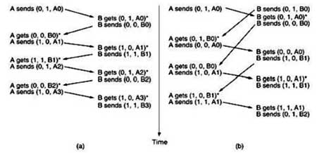
Fig.9.2 Two scenarios for protocol 4 (a) Normal case (b) Abnormal case. The notation is (seq, ack, packet number). An asterisk indicates where a network layer accepts a packet.
4.1.2 Selective repeat:
A Protocol Using Go Back N:
Until now we have made the tacit assumption that the transmission time required for a frame to arrive at the receiver plus the transmission time for the acknowledgement to come back is negligible. Sometimes this assumption is clearly false. In these situations, the long round-trip time can have important implications for the efficiency of the bandwidth utilization. As an example, consider a 50-kbps satellite channel with a 500-msec round-trip propagation delay. Let’s imagine trying to use protocol 4 to send 1000-bit frames via the satellite. At t = 0 the sender starts sending the first frame. At t = 20 msec the frame has been completely sent. Not until t =270 msec has the frame fully arrived at the receiver, and not until t = 520msec has the acknowledgement arrived back at the sender, under the best of circumstances (no waiting in the receiver and a short acknowledgement frame). This means that the sender was blocked during 500/520 or 96 percent of the time. In other words, only 4 percent of the available bandwidth was used. Clearly, the combination of a long transit time, high bandwidth, and short frame length is disastrous in terms of efficiency. The problem described above can be viewed as a consequence of the rule requiring a sender to wait for an acknowledgement before sending another frame. If we relax that restriction, much better efficiency can be achieved. Basically, the solution lies in allowing the sender to transmit up to w frames before blocking, instead of just 1. With an appropriate choice of w the sender will be able to continuously transmit frames for a time equal to the round-trip transit time without filling up the window. In the example above, w should be at least 26. The sender begins sending frame 0 as before. By the time it has finished sending 26 frames, at t = 520, the acknowledgement for frame 0 will have just arrived. Thereafter, acknowledgements arrive every 20 msec, so the sender always gets permission to continue just when it needs it. At all times, 25 or 26 unacknowledged frames are outstanding. Put in other terms, the sender's maximum window size is 26.
The need for a large window on the sending side occurs whenever the product of bandwidth x round-trip-delay is large. If the bandwidth is high, even for a moderate delay, the sender will exhaust its window quickly unless it has a large window. If the delay is high (e.g., on a geostationary satellite channel), the sender will exhaust its window even for a moderate bandwidth. The product of these two factors basically tells what the capacity of the pipe is, and the sender needs the ability to fill it without stopping in order to operate at peak efficiency. This technique is known as pipelining. If the channel capacity is b bits/sec, the frame size l bits, and the round-trip propagation time R sec, the time required to transmit a single frame is l/b sec. After the last bit of a data frame has been sent, there is a delay of R/2 before that bit arrives at the receiver and another delay of at least R/2 for the acknowledgement to come back, for a total delay of R. In stop-and-wait the line is busy for l/band idle for R, giving. If l < bR, the efficiency will be less than 50 percent. Since there is always a nonzero delay for the acknowledgement to propagate back, pipelining can, in principle, be used to keep the line busy during this interval, but if the interval is small, the additional complexity is not worth the trouble. Pipelining frames over an unreliable communication channel raises some serious issues. First, what happens if a frame in the middle of a long stream is damaged or lost? Large numbers of succeeding frames will arrive at the receiver before the sender even finds out that anything is wrong. When a damaged frame arrives at the receiver, it obviously should be discarded, but what should the receiver do with all the correct frames following it? Remember that the receiving data link layer is obligated to hand packets to the network layer in sequence. In Two basic approaches are available for dealing with errors in the presence of pipelining. One way, called go back n, is for the receiver simply to discard all subsequent frames, sending no acknowledgements for the discarded frames. This strategy corresponds to a receive window of size 1. In other words, the data link layer refuses to accept any frame except the next one it must give to the network layer. If the sender's window fills up before the timer runs out, the pipeline will begin to empty. Eventually, the sender will time out and retransmit all unacknowledged frames in order, starting with the damaged or lost one. This approach can waste a lot of bandwidth if the error rate is high.
In Fig.10.1 (a) we see go back n for the case in which the receiver's window is large. Frames 0 and 1 are correctly received and acknowledged. Frame 2, however, is damaged or lost. The sender, unaware of this problem, continues to send frames until the timer for frame 2 expires. Then it backs up to frame 2 and starts all over with it, sending 2, 3, 4, etc. all over again. The other general strategy for handling errors when frames are pipelined is called selective repeat. When it is used, a bad frame that is received is discarded, but good frames received after it are buffered. When the sender times out, only the oldest unacknowledged frame is retransmitted. If that frame arrives correctly, the receiver can deliver to the network layer, in sequence, all the frames it has buffered. Selective repeat is often combined with having the receiver send a negative acknowledgement (NAK) when it detects an error, for example, when it receives a checksum error or a frame out of sequence. NAKs stimulate retransmission before the corresponding timer expires and thus improve performance. In Fig.10.1 (b), frames 0 and 1 are again correctly received and acknowledged and frame 2 is lost. When frame 3 arrives at the receiver, the data link layer there notices that is has missed a frame, so it sends back a NAK for 2 but buffers 3. When frames 4 and 5 arrive, they, too, are buffered by the data link layer instead of being passed to the network layer. Eventually, the NAK 2 gets back to the sender, which immediately resends frame 2. When that arrives, the data link layer now has 2, 3, 4, and 5 and can pass all of them to the network layer in the correct order. It can also acknowledge all frames up to and including 5, as shown in the figure. If the NAK should get lost, eventually the sender will time out for frame 2 and send it (and only it) of its own accord, but that may be a quite a while later. In effect, the NAK speeds up the retransmission of one specific frame.
Selective repeat corresponds to a receiver window larger than 1. Any frame within the window may be accepted and buffered until all the preceding ones have been passed to the network layer. This approach can require large amounts of data link layer memory if the window is large. These two alternative approaches are trade-offs between bandwidth and data link layer buffer space. Depending on which resource is scarcer, one or the other can be used. Figure 10.2 shows a pipelining protocol in which the receiving data link layer only accepts frames in order; frames following an error are discarded. In this protocol, for the first time we have dropped the assumption that the network layer always has an infinite supply of packets to send. When the network layer has a packet it wants to send, it can cause a network_layer_ready event to happen. However, to enforce the flow control rule of no more than MAX_SEQ unacknowledged frames outstanding at any time, the data link layer must be able to keep the network layer from bothering it with more work. The library procedures enable_network_layer and disable_network_layer do this job.
A Protocol Using Selective Repeat
This protocol works well if errors are rare, but if the line is poor, it wastes a lot of bandwidth on retransmitted frames. An alternative strategy for handling errors is to allow the receiver to accept and buffer the frames following a damaged or lost one. Such a protocol does not discard frames merely because an earlier frame was damaged or lost. In this protocol, both sender and receiver maintain a window of acceptable sequence numbers. The sender's window size starts out at 0 and grows to some predefined maximum, MAX_SEQ. The receiver's window, in contrast, is always fixed in size and equal to MAX_SEQ. The receiver has a buffer reserved for each sequence number within its fixed window. Associated with each buffer is a bit (arrived) telling whether the buffer is full or empty. Whenever a frame arrives, its sequence number is checked by the function between to see if it falls within the window. If so and if it has not already been received, it is accepted and stored. This action is taken without regard to whether or not it contains the next packet expected by the network layer. Of course, it must be kept within the data link layer and not passed to the network layer until all the lower-numbered frames have already been delivered to the network layer in the correct order.
4.2 HDLC—High-Level Data Link Control:
These are a group of closely related protocols that are a bit old but are still heavily used. They are all derived from the data link protocol first used in the IBM mainframe world: SDLC (Synchronous Data Link Control) protocol. After developing SDLC, IBM submitted it to ANSI and ISO for acceptance as U.S. and international standards, respectively. ANSI modified it to become ADCCP (Advanced Data Communication Control Procedure), and ISO modified it to become HDLC (High-level Data Link Control). CCITT then adopted and modified HDLC for its LAP (Link Access Procedure) as part of the X.25 network interface standard but later modified it again to LAPB, to make it more compatible with a later version of HDLC. The nice thing about standards is that you have so many to choose from. Furthermore, if you do not like any of them, you can just wait for next year's model. These protocols are based on the same principles. All are bit oriented, and all use bit stuffing for data transparency. They differ only in minor, but nevertheless irritating, ways. The discussion of bit-oriented protocols that follows is intended as a general introduction. For the specific details of any one protocol, please consult the appropriate definition.
All the bit-oriented protocols use the frame structure shown in Fig.11.1. The Address field is primarily of importance on lines with multiple terminals, where it is used to identify one of the terminals. For point-to-point lines, it is sometimes used to distinguish commands from responses.
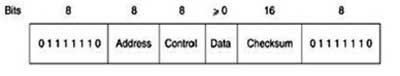
Fig.11.1. Frame format for bit-oriented protocols
The Control field is used for sequence numbers, acknowledgements, and other purposes, as discussed below. The Data field may contain any information. It may be arbitrarily long, although the efficiency of the checksum falls off with increasing frame length due to the greater probability of multiple burst errors.
The Checksum field is a cyclic redundancy code. The frame is delimited with another flag sequence (01111110). On idle point-to-point lines, flag sequences are transmitted continuously. The minimum frame contains three fields and totals 32 bits, excluding the flags on either end. There are three kinds of frames: Information, Supervisory, and Unnumbered.
The contents of the Control field for these three kinds are shown in Fig.11.2. The protocol uses a sliding window, with a 3-bit sequence number. Up to seven unacknowledged frames may be outstanding at any instant. The Seq field in Fig.11.2 (a) is the frame sequence number. The Next field is a piggybacked acknowledgement. However, all the protocols adhere to the convention that instead of piggybacking the number of the last frame received correctly, they use the number of the first frame not yet received (i.e., the next frame expected). The choice of using the last frame received or the next frame expected is arbitrary; it does not matter which convention is used, provided that it is used consistently.
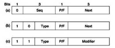
Fig.11.2 Control field of (a) an information frame, (b) a supervisory frame, (c) an unnumbered frame
The P/F bit stands for Poll/Final. It is used when a computer (or concentrator) is polling a group of terminals. When used as P, the computer is inviting the terminal to send data. All the frames sent by the terminal, except the final one, have the P/F bit set to P. The final one is set to F. In some of the protocols, the P/F bit is used to force the other machine to send a Supervisory frame immediately rather than waiting for reverse traffic onto which to piggyback the window information. The bit also has some minor uses in connection with the unnumbered frames.
The various kinds of Supervisory frames are distinguished by the Type field. Type 0 is an acknowledgement frame (officially called RECEIVE READY) used to indicate the next frame expected. This frame is used when there is no reverse traffic to use for piggybacking.
Type 1 is a negative acknowledgement frame (officially called REJECT). It is used to indicate that a transmission error has been detected. The Next field indicates the first frame in sequence not received correctly (i.e., the frame to be retransmitted). The sender is required to retransmit all outstanding frames starting at Next. This strategy is similar to our protocol 5 rather than our protocol 6.
Type 2 is RECEIVE NOT READY. It acknowledges all frames up to but not including Next, just as RECEIVE READY does, but it tells the sender to stop sending. RECEIVE NOT READY is intended to signal certain temporary problems with the receiver, such as a shortage of buffers, and not as an alternative to the sliding window flow control. When the condition has been repaired, the receiver sends a RECEIVE READY, REJECT, or certain control frames.
Type 3 is the SELECTIVE REJECT. It calls for retransmission of only the frame specified. In this sense, it is like our protocol 6 rather than 5 and is therefore, most useful when the sender's window size is half the sequence space size, or less. Thus, if a receiver wishes to buffer out- of- sequence frames for potential future use, it can force the retransmission of any specific frame using Selective Reject. HDLC and ADCCP allow this frame type, but SDLC and LAPB do not allow it (i.e., there is no Selective Reject) and type 3 frames are undefined.
The third class of frame is the unnumbered frame. It is sometimes used for control purposes but can also carry data when unreliable connectionless service is called for. The various bit-oriented protocols differ considerably here, in contrast with the other two kinds, where they are nearly identical. Five bits are available to indicate the frame type, but not all 32 possibilities are used.
4.3 PPP-The Point-to-Point Protocol:
The Internet needs a point-to-point protocol for a variety of purposes, including router-to- router traffic and home user-to-ISP traffic. This protocol is PPP (Point-to-Point Protocol), which is defined in RFC 1661 and further elaborated on in several other RFCs (e.g., RFCs 1662 and 1663). PPP handles error detection, supports multiple protocols, allows IP addresses to be negotiated at connection time, permits authentication, and has many other features.
PPP provides three features:
- A framing method that unambiguously delineates the end of one frame and the start of the next one. The frame format also handles error detection.
- A link control protocol for bringing lines up, testing them, negotiating options, and bringing them down again gracefully when they are no longer needed. This protocol is called LCP (Link Control Protocol). It supports synchronous and asynchronous circuits and byte-oriented and bit- oriented encodings.
- A way to negotiate network-layer options in a way that is independent of the network layer protocol to be used. The method chosen is to have a different NCP (Network Control Protocol) for each network layer supported.
To see how these pieces fit together, let us consider the typical scenario of a home user calling up an Internet service provider to make a home PC a temporary Internet host. The PC first calls the provider's router via a modem. After the router's modem has answered the phone and established a physical connection, the PC sends the router a series of LCP packets in the payload field of one or more PPP frames. These packets and their responses select the PPP parameters to be used.
Once the parameters have been agreed upon, a series of NCP packets are sent to configure the network layer. Typically, the PC wants to run a TCP/IP protocol stack, so it needs an IP address. There are not enough IP addresses to go around, so normally each Internet provider gets a block of them and then dynamically assigns one to each newly attached PC for the duration of its login session. If a provider owns n IP addresses, it can have up to n machines logged in simultaneously, but its total customer base may be many times that. The NCP for IP assigns the IP address. At this point, the PC is now an Internet host and can send and receive IP packets, just as hardwired hosts can. When the user is finished, NCP tears down the network layer connection and frees up the IP address. Then LCP shuts down the data link layer connection. Finally, the computer tells the modem to hang up the phone, releasing the physical layer connection.
The PPP frame format was chosen to closely resemble the HDLC frame format, since there was no reason to reinvent the wheel. The major difference between PPP and HDLC is that PPP is character oriented rather than bit oriented. In particular, PPP uses byte stuffing on dial-up modem lines, so all frames are an integral number of bytes. It is not possible to send a frame consisting of 30.25 bytes, as it is with HDLC. Not only can PPP frames be sent over dialup telephone lines, but they can also be sent over SONET or true bit-oriented HDLC lines (e.g., for router-router connections). The PPP frame format is shown in Fig.13.
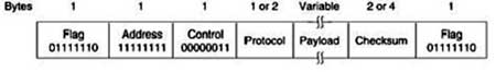
Fig.13. The PPP full frame format for unnumbered mode operation
All PPP frames begin with the standard HDLC flag byte (01111110), which is byte stuffed if it occurs within the payload field. Next comes the Address field, which is always set to the binary value 11111111 to indicate that all stations are to accept the frame. Using this value avoids the issue of having to assign data link addresses.
The Address field is followed by the Control field, the default value of which is 00000011. This value indicates an unnumbered frame. In other words, PPP does not provide reliable transmission using sequence numbers and acknowledgements as the default. In noisy environments, such as wireless networks, reliable transmission using numbered mode can be used. The exact details are defined in RFC 1663, but in practice it is rarely used. Since the Address and Control fields are always constant in the default configuration, LCP provides the necessary mechanism for the two parties to negotiate an option to just omit them altogether and save 2 bytes per frame.
The fourth PPP field is the Protocol field. Its job is to tell what kind of packet is in the Payload field. Codes are defined for LCP, NCP, IP, IPX, AppleTalk, and other protocols. Protocols starting with a 0 bit are network layer protocols such as IP, IPX, OSI CLNP, XNS. Those starting with a 1 bit are used to negotiate other protocols. These include LCP and a different NCP for each network layer protocol supported. The default size of the Protocol field is 2 bytes, but it can be negotiated down to 1 byte using LCP. The Payload field is variable length, up to some negotiated maximum. If the length is not negotiated using LCP during line setup, a default length of 1500 bytes is used. Padding may follow the payload if need be. After the Payload field comes the Checksum field, which is normally 2 bytes, but a 4-byte checksum can be negotiated. In summary, PPP is a multiprotocol framing mechanism suitable for use over modems, HDLC bit-serial lines, SONET, and other physical layers. It supports error detection, option negotiation, header compression, and, optionally, reliable transmission using an HDLC type frame format.
Published date : 25 Jul 2015 04:35PM