

Sakshi Education
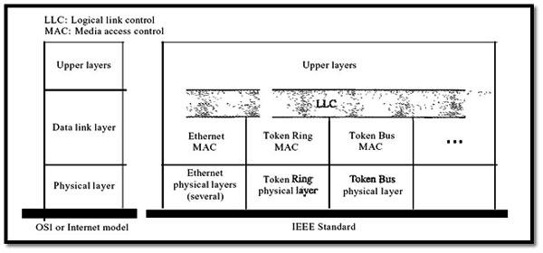
The 802 standard was developed by IEEE computer society to set standards for the intercommunications systems and later approved by ANSI and ISO 8802. It is a way of specifying functions of the physical layer and the data link layer of major LAN protocols. The relationship of the 802 Standard to the traditional OSI model is shown in Figure 1.
The IEEE has subdivided the data link layer into two sub layers:
The IEEE has subdivided the data link layer into two sub layers:
- Logical link control (LLC) and media access control (MAC).
- IEEE has also created several physical layer standards for different LAN protocols.
Figure 1: IEEE standard for LANs
6.1.1 Data Link Layer
As we mentioned before, the data link layer in the IEEE standard is divided into two sub layers: LLC and MAC.
Logical Link Control (LLC)
In IEEE Project 802, flow control, error control, and part of the framing duties are collected into one sub layer called the logical link control. Framing is handled in both the LLC sub layer and the MAC sub layer.
One single data link control protocol is provided by LLC for all IEEE LANs. A single LLC protocol can provide interconnectivity between different LANs because it makes the MAC sub layer transparent.
Framing LLC defines a protocol data unit (PDU) that is somewhat similar to that of HDLC. The header contains a control field like the one in HDLC; this field is used for flow and error control. The two other header fields define the upper-layer protocol at the source and destination that uses LLC. These fields are called the destination service access point (DSAP) and the source service access point (SSAP). The other fields defined in a typical data link control protocol such as HDLC are moved to the MAC sub layer. In other words, a frame defined in HDLC is divided into a PDU at the LLC sub layer and a frame at the MAC sub layer, as shown in Figure 2.
Need for LLC: The purpose of the LLC is to provide flow and error control for the upper-layer protocols that actually demand these services. For example, if a LAN or several LANs are used in an isolated system, LLC may be needed to provide flow and error control for the application layer protocols. However, most upper-layer protocols such as IP, do not use the services of LLC.
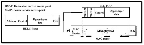
Figure 13.2 HDLC frame compared with LLC and MAC frames
Media Access Control (MAC)
IEEE Project 802 has created a sub layer called media access control that defines the specific access method for each LAN. As we discussed in the previous section, part of the framing function is also handled by the MAC layer. In contrast to the LLC sub layer, the MAC sub layer contains a number of distinct modules; each defines the access method and the framing format specific to the corresponding LAN protocol.
6.1.2 Physical Layer
The physical layer is dependent on the implementation and type of physical media used. IEEE defines detailed specifications for each LAN implementation. For example, although there is only one MAC sub layer for Standard Ethernet, there is a different physical layer specification for each Ethernet implementations.
6.2 Standard Ethernet
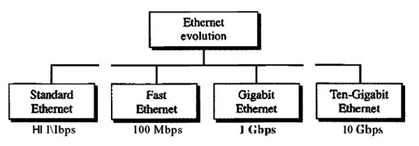
Figure 3 Ethernet evolutions through four generations
6.2.1 MAC Sublayer
In Standard Ethernet, the MAC sub layer governs the operation of the access method. It also frames data received from the upper layer and passes them to the physical layer.
Frame Format
The Ethernet frame contains seven fields: preamble, SFD, DA, SA, length or type of protocol data unit (PDU), upper-layer data, and the CRC. Ethernet does not provide any mechanism for acknowledging received frames, making it what is known as an unreliable medium. Acknowledgments must be implemented at the higher layers. The format of the MAC frame is shown in Figure 4.
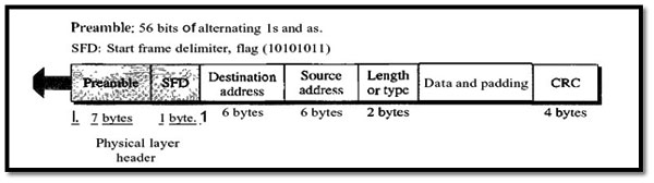
Figure4: 802.3 MAC frame
D Preamble: The first field of the 802.3 frame contains 7 bytes (56 bits) of alternating O’s and I’s that alerts the receiving system to the coming frame and enables it to synchronize its input timing. The pattern provides only an alert and a timing pulse. The 56-bit pattern allows the stations to miss some bits at the beginning of the frame. The preamble is actually added at the physical layer and is not (formally) part of the frame.
D Start frame delimiter (SFD): The second field (l byte: 10101011) signals the beginning of the frame. The SFD warns the station or stations that this is the last chance for synchronization. The last 2 bits is 11 and alerts the receiver that the next field is the destination address.
Destination address (DA): The DA field is 6 bytes and contains the physical address of the destination station or stations to receive the packet.
Source address (SA): The SA field is also 6 bytes and contains the physical address of the sender of the packet. We will discuss addressing shortly.
Length or type: This field is defined as a type field or length field. The original Ethernet used this field as the type field to define the upper-layer protocol using the MAC frame. The IEEE standard used it as the length field to define the number of bytes in the data field.
Data: This field carries data encapsulated from the upper-layer protocols. It is a minimum of 46 and a maximum of 1500 bytes.
CRC: The last field contains error detection information, in this case a CRC-32.
Frame Length: Ethernet has imposed restrictions on both the minimum and maximum lengths of a frame, as shown in Figure 5.
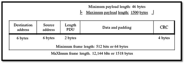
Figure 5 Minimum and maximum lengths
An Ethernet frame needs to have a minimum length of 512 bits or 64 bytes. Part of this length is the header and the trailer. If we count 18 bytes of header and trailer (6 bytes of source address, 6 bytes of destination address, 2 bytes of length or type, and 4 bytes of CRC), then the minimum length of data from the upper layer is 64 - 18 = 46 bytes. If the upper-layer packet is less than 46 bytes, padding is added to make up the difference.
The standard defines the maximum length of a frame as 1518 bytes. If we subtract the 18 bytes of header and trailer, the maximum length of the payload is 1500 bytes.
The maximum length restriction has two historical reasons. First, memory was very expensive when Ethernet was designed: a maximum length restriction helped to reduce the size of the buffer. Second, the maximum length restriction prevents one station from monopolizing the shared medium, blocking other stations that have data to send.
Frame length: Minimum: 64 bytes (512 bits) Maximum: 1518 bytes (12,144 bits)
Addressing: Each station on an Ethernet network (such as a PC, workstation, or printer) has its own network interface card (NIC). The NIC fits inside the station and provides the station with a 6-byte physical address. As shown in Figure 6, the Ethernet address is 6 bytes (48 bits), nonnally written in hexadecimal notation, with a colon between the bytes.
06:01 :02:01:2C:4B
6 bytes =12 hex digits =48 bits
Unicast, Multicast, and Broadcast Addresses A source address is always a unicast address-the frame comes from only one station. The destination address, however, can be unicast, multicast, or broadcast. Figure 7 shows how to distinguish a unicast address from a multicast address. If the least significant bit of the first byte in a destination address is 0, the address is unicast; otherwise, it is multicast.
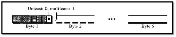
Figure 7 Unicast and multicast addresses
A unicast destination address defines only one recipient; the relationship between the sender and the receiver is one-to-one. A multicast destination address defines a group of addresses; the relationship between the sender and the receivers is one-to-many. The broadcast address is a special case of the multicast address; the recipients are all the stations on the LAN. A broadcast destination address is forty-eight.
6.2.2 Physical Layer
The Standard Ethernet defines several physical layer implementations; four of the most common, are shown in Figure 8.
Encoding and Decoding
All standard implementations use digital signaling (baseband) at 10 Mbps. At the sender, data are converted to a digital signal using the Manchester scheme; at the receiver, the received signal is interpreted as Manchester and decoded into data. Manchester encoding is self-synchronous, providing a transition at each bit interval. Figure 9 shows the encoding scheme for Standard Ethernet.
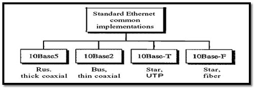
Figure 8: Categories of Standard Ethernet
6.3 Fast Ethernet
Fast Ethernet was designed to compete with LAN protocols such as FDDI or Fiber Channel (or Fiber Channel, as it is sometimes spelled). IEEE created Fast Ethernet under the name 802.3u. Fast Ethernet is backward-compatible with Standard Ethernet, but it can transmit data 10 times faster at a rate of 100 Mbps. The goals of Fast Ethernet can be summarized as follows:
- Upgrade the data rate to 100 Mbps.
- Make it compatible with Standard Ethernet.
- Keep the same 48-bit address.
- Keep the same frame format.
- Keep the same minimum and maximum frame lengths.
- MAC Sub layer
- Physical Layer
6.4 IEEE 802.11
6.4.1 Architecture
The standard defines two kinds of services: the basic service set (BSS) and the extended service set (ESS).
Basic Service Set
IEEE 802.11 defines the basic service set (BSS) as the building block of a wireless LAN. A basic service set is made of stationary or mobile wireless stations and an optional central base station, known as the Access Point (AP). Figure 9 shows two sets in this standard.
The BSS without an AP is a stand-alone network and cannot send data to other BSSs. It is called an ad hoc architecture. In this architecture, stations can form a network without the need of an AP; they can locate one another and agree to be part of a BSS. A BSS with an AP is sometimes referred to as an infrastructure network.
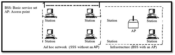
Figure9: Basic service sets (BSSs)
Extended Service Set:
An extended service set (ESS) is made up of two or more BSSs with APs. In this case, the BSSs are connected through a distribution system, which is usually a wired LAN. The distribution system connects the APs in the BSSs. IEEE 802.11 does not restrict the distribution system; it can be any IEEE LAN such as an Ethernet. Note that the extended service set uses two types of stations: mobile and stationary. The mobile stations are normal stations inside a BSS. The stationary stations are AP stations that are part of a wired LAN. Figure 10 shows an ESS.
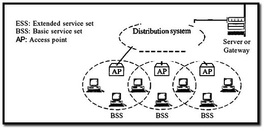
Figure10: Extended service sets (ESSs)
Published date : 17 Jul 2015 02:54PM