

Sakshi Education

History of Data base Systems:
Data base design and ER diagrams:
Relationship Set: A set of relationships of similar type is called a relationship set. Like entities, a relationship too can have attributes. These attributes are called descriptive attributes. Degree of Relationship: The number of participating entities in a relationship defines the degree of the relationship.
Mapping Cardinalities: Cardinality defines the number of entities in one entity set, which can be associated with the number of entities of other set via relationship set.
Attributes and Entity sets:
Entity Type: Set of similar objects or a category of entities; they are well defined
Attribute: Describes one aspect of an entity type; usually [and best when] single valued and indivisible (atomic)
Relationships and Relationship sets:
ER Model Basics:
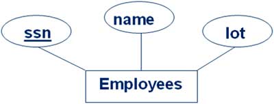
Entity: Real-world objects distinguishable from other objects. An entity is described (in DB) using a set of attributes. Entity Set: A collection of similar entities. E.g., all employees
Conceptual Design for Large enterprises: The purpose of the conceptual design phase is to build a conceptual model based upon the previously identified requirements, but closer to the final physical model. A commonly-used conceptual model is called an entity-relationship model. Entities are basically people, places, or things you want to keep information about. For example, a library system may have the book, library and borrower entities. Learning to identify what should be an entity, what should be a number of entities, and what should be an attribute of an entity takes practice, but there are some good rules of thumb. The following questions can help to identify whether something is an entity:
- Data Base Management Systems (DBMSs) have played an outsized role in the history of software development and in the creation and growth of the software products industry.
- The issues will be the fourth and fifth sponsored by the Software Industry Special Interest Group of the Computer History Museum (formerly the Software History Centre).
- This issue (the first) is focused on the products, companies, and people who designed, programmed, and sold mainframe DBMS software products beginning in the 1960s and 1970s.
- The second issue will be devoted to the relational DBMS products, which were developed during the 1970s and came to prominence (and some say dominance) during the 1980s and 1990s.
- Thomas Haigh begins this issue by describing the world prior to DBMSs and some of the early DBMS products. Tim Bergin and Thomas Haigh then examine the database management products that dominated the IBM environment and other major computer platforms in the 1970s and 1980s.
Data base design and ER diagrams:
- The association among entities is called a relationship. For example, an employee works_at a department, a student enrolls in a course. Here, Works_at and enrolls are called relationships.
Relationship Set: A set of relationships of similar type is called a relationship set. Like entities, a relationship too can have attributes. These attributes are called descriptive attributes. Degree of Relationship: The number of participating entities in a relationship defines the degree of the relationship.
- Binary = degree 2
- Ternary = degree 3
- n-ary = degree
Mapping Cardinalities: Cardinality defines the number of entities in one entity set, which can be associated with the number of entities of other set via relationship set.
- One-to-one – One entity from entity set A can be associated with at most one entity of entity set B and vice versa.
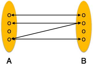
- One-to-many – One entity from entity set A can be associated with more than one entities of entity set B however an entity from entity set B, can be associated with at most one entity.
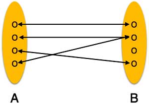
- Many-to-one – More than one entities from entity set A can be associated with at most one entity of entity set B, however an entity from entity set B can be associated with more than one entity from entity set A.
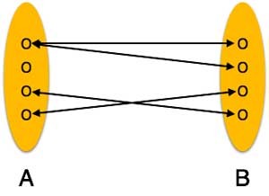
- Many-to-many – One entity from A can be associated with more than one entity from B and vice versa.
- Can be person, place, event, object, concept in the real world
- Can be physical object or abstraction
- Ex: "John", "CSE305"
Attributes and Entity sets:
Entity Type: Set of similar objects or a category of entities; they are well defined
- A rectangle represents an entity set
- Ex: students, courses
- We often just say "entity" and mean "entity type"
Attribute: Describes one aspect of an entity type; usually [and best when] single valued and indivisible (atomic)
- Represented by oval on E-R diagram
- Ex: name, maximum enrolment
- May be multi-valued – use double oval on E-R diagram
- May be composite – attribute has further structure; also use oval for composite attribute, with ovals for components connected to it by lines
- May be derived – a virtual attribute, one that is computable from existing data in the database, use dashed oval. This helps reduce redundancy.
Relationships and Relationship sets:
- After two or more entities are identified and defined with attributes, the participants determine if a relationship exists between the entities. A relationship is any association, linkage, or connection between the entities of interest to the business; it is a two-directional, significant association between two entities, or between an entity and itself.Each relationship has a name, an optionality (optional or mandatory), and a degree (how many). A relationship is described in real terms.
- Assigning a name, optionality, and a degree to a relationship helps confirm the validity of that relationship. If you cannot give a relationship all these things, then perhaps there really is no relationship at all.
- Relationship represents an association between two or more entities. An example of a relationship would be:
- Employees are assigned to projects
- Projects have subtasks
- Departments manage one or more projects
- Relationships are the connections and interactions between the entities instances e.g. DEPT_EMP associates Department and Employee.
- A relationship type is an abstraction of a relationship i.e. a set of relationships instances sharing common attributes.
Concept Design with the ER Model:
Conceptual design: (ER Model is used at this stage.)
Conceptual design: (ER Model is used at this stage.)
- What are the entities and relationships in the enterprise?
- What information about these entities and relationships should we store in the database?
- What are the integrity constraints or business rules that hold?
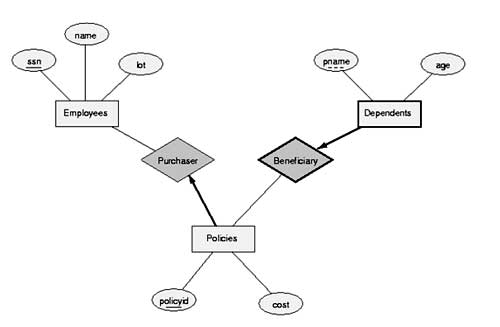
- A database ‘schema’ in the ER Model can be represented pictorially (ER diagrams).
- Can map an ER diagram into a relational schema.
ER Model Basics:
Entity: Real-world objects distinguishable from other objects. An entity is described (in DB) using a set of attributes. Entity Set: A collection of similar entities. E.g., all employees
- All entities in an entity set have the same set of attributes. (Until we consider ISA hierarchies, anyway!)
- Each entity set has a key.
- Each attribute has a domain.
Conceptual Design for Large enterprises: The purpose of the conceptual design phase is to build a conceptual model based upon the previously identified requirements, but closer to the final physical model. A commonly-used conceptual model is called an entity-relationship model. Entities are basically people, places, or things you want to keep information about. For example, a library system may have the book, library and borrower entities. Learning to identify what should be an entity, what should be a number of entities, and what should be an attribute of an entity takes practice, but there are some good rules of thumb. The following questions can help to identify whether something is an entity:
- Can it vary in number independently of other entities? For example, person height is probably not an entity, as it cannot vary in number independently of person. It is not fundamental, so it cannot be an entity in this case.
- Is it important enough to warrant the effort of maintaining? For example customer may not be important for a small grocery store and will not be an entity in that case, but it will be important for a video store, and will be an entity in that case.
- Is it its own thing that cannot be separated into subcategories? For example, a car-rental agency may have different criteria and storage requirements for different kinds of vehicles. Vehicle may not be an entity, as it can be broken up into car and boat, which are the entities.
- Does it list a type of thing, not an instance? The video game blow-em-up 6 is not an entity, rather an instance of the game entity.
- Does it have many associated facts? If it only contains one attribute, it is unlikely to be an entity. For example, city may be an entity in some cases, but if it contains only one attribute, city name, it is more likely to be an attribute of another entity, such as customer.
- Course (name, code, course prerequisites)
- Student (first_name, surname, address, age)
- Book (title, ISBN, price, quantity in stock)
Published date : 01 Jun 2016 05:46PM