


If we look back the invention of internet idea, sharing of data stays pivotal. Thus we can state that internet is a communication system that has brought a wealth of information to our finger tips and organized it for our use. In fact internet has revolutionized the complete communication systems.
Internet History time line:
As per the sources of live science, the timeline of internet is as follows:
- 1934: Belgian information expert named Paul Otlet imagined a “Radiated Library” that would use technology of the day — the telephone and radio — to create something very much like the Internet.
- 1965: Two computers at MIT Lincoln Lab communicate with one another using packet-switching technology.
- 1968: Beranek and Newman, Inc. (BBN) unveils the final version of the Interface Message Processor (IMP) specifications. BBN wins ARPANET contract.
- 1969: On Oct. 29, UCLA’s Network Measurement Center, Stanford Research Institute (SRI), University of California-Santa Barbara and University of Utah install nodes. The first message is “LO,” which was an attempt by student Charles Kline to “LOGIN” to the SRI computer from the university. However, the message was unable to be completed because the SRI system crashed.
- 1972: BBN’s Ray Tomlinson introduces network email. The Internetworking Working Group (INWG) forms to address need for establishing standard protocols.
- 1973: Global networking becomes a reality as the University College of London (England) and Royal Radar Establishment (Norway) connect to ARPANET. The term Internet is born.
- 1974: The first Internet Service Provider (ISP) is born with the introduction of a commercial version of ARPANET, known as Telenet.
- 1974: Vinton Cerf and Bob Kahn (the duo said by many to be the Fathers of the Internet) publish "A Protocol for Packet Network Interconnection," which details the design of TCP.
- 1976: Queen Elizabeth II hits the “send button” on her first email.
- 1979: USENET forms to host news and discussion groups.
- 1981: The National Science Foundation (NSF) provided a grant to establish the Computer Science Network (CSNET) to provide networking services to university computer scientists.
- 1982: Transmission Control Protocol (TCP) and Internet Protocol (IP), as the protocol suite, commonly known as TCP/IP, emerge as the protocol for ARPANET. This results in the fledgling definition of the Internet as connected TCP/IP internets. TCP/IP remains the standard protocol for the Internet.
- 1983: The Domain Name System (DNS) establishes the familiar .edu, .gov, .com, .mil, .org, .net, and .int system for naming websites. This is easier to remember than the previous designation for websites, such as 123.456.789.10.
- 1984: William Gibson, author of "Neuromancer," is the first to use the term "cyberspace."
- 1985: Symbolics.com, the website for Symbolics Computer Corp. in Massachusetts, becomes the first registered domain.
- 1986: The National Science Foundation’s NSFNET goes online to connected supercomputer centers at 56,000 bits per second — the speed of a typical dial-up computer modem. Over time the network speeds up and regional research and education networks, supported in part by NSF, are connected to the NSFNET backbone — effectively expanding the Internet throughout the United States. The NSFNET was essentially a network of networks that connected academic users along with the ARPANET.
- 1987: The number of hosts on the Internet exceeds 20,000. Cisco ships its first router.
- 1989: World.std.com becomes the first commercial provider of dial-up access to the Internet.
- 1990: Tim Berners-Lee, a scientist at CERN, the European Organization for Nuclear Research, develops HyperText Markup Language (HTML). This technology continues to have a large impact on how we navigate and view the Internet today.
- 1991: CERN introduces the World Wide Web to the public.
- 1992: The first audio and video are distributed over the Internet. The phrase “surfing the Internet” is popularized.
- 1993: The number of websites reaches 600 and the White House and United Nations go online. Marc Andreesen develops the Mosaic Web browser at the University of Illinois, Champaign-Urbana. The number of computers connected to NSFNET grows from 2,000 in 1985 to more than 2 million in 1993. The National Science Foundation leads an effort to outline a new Internet architecture that would support the burgeoning commercial use of the network.
- 1994: Netscape Communications is born. Microsoft creates a Web browser for Windows 95.
- 1995: Compuserve, America Online and Prodigy begin to provide Internet access. Amazon.com, Craigslist and eBay go live. The original NSFNET backbone is decommissioned as the Internet’s transformation to a commercial enterprise is largely completed.
- 1996: The browser war, primarily between the two major players Microsoft and Netscape, heats up. CNET buys tv.com for $15,000.
- 1997: PC makers can remove or hide Microsoft’s Internet software on new versions of Windows 95, thanks to a settlement with the Justice Department. Netscape announces that its browser will be free.
- 1998: The Google search engine is born, changing the way users engage with the Internet.
- 1999: AOL buys Netscape. Peer-to-peer file sharing becomes a reality as Napster arrives on the Internet, much to the displeasure of the music industry.
- 2000: The dot-com bubble bursts. Web sites such as Yahoo! and eBay are hit by a large-scale denial of service attack, highlighting the vulnerability of the Internet. AOL merges with Time Warner.
- 2001: A federal judge shuts down Napster, ruling that it must find a way to stop users from sharing copyrighted material before it can go back online.
- 2003: The SQL Slammer worm spread worldwide in just 10 minutes. Myspace, Skype and the Safari Web browser debut.
- 2004: Facebook goes online and the era of social networking begins. Mozilla unveils the Mozilla Firefox browser.
- 2005: YouTube.com launches.
- 2006: AOL changes its business model, offering most services for free and relying on advertising to generate revenue. The Internet Governance Forum meets for the first time.
Let’s get more close to few terminologies before we get in to subject
Protocol
A protocol is a set of rules (conventions) that govern all aspects of data communication.
Data: is a representation of facts, concepts and instructions presented in a formalized manner suitable for communication, interpretation or processing by human beings or by automatic means.
Information: is currently assigned to data by means by the conventions applied to those data.
Network: Network is a anthology of computers associated to each other. It allows the computers to communicate with each other and sh resources which include information, software and peripheral devices such as printers, scanners
Computer networks: Computer network is an interconnection of two or more computers and peripherals such as printers and faxes. Computer network allows the user to share and transfer information using cables or modems within a network.
Data Communication: Data Communication is the exchange of data (in the form of Os and 1s) between two devices via some form of transmission medium (such as a wire cable). The important components of data communication are:
- Message – the message is the information to be communicated.
- Sender – the sender is the device that sends the data message.
- Receiver – the receiver is the devices that receive the message.
- Medium – the transmission medium is the physical path by which a message travels from sender to receiver.
Internetworking
The art and science of connecting individual local-area networks (LANs) to create wide-area Networks (WANs), and connecting WANs to form even larger WANs. Internetworking can be extremely complex because it generally involves connecting networks that use different protocols. Internetworking is accomplished with routers, bridges, and gateways.
Routing
It is the process of moving a packet of data from source to destination. Routing is usually performed by a dedicated device called a router. Routing is a key feature of the Internet because it enables messages to pass from one computer to another and eventually reach the target machine. Each intermediary computer performs routing by passing along the message to the next computer. Part of this process involves analyzing a routing table to determine the best path.
Media
In computer networks, media refers to the cables linking workstations together. There are many different types of transmission media, the most popular being twisted-pair wire (normal electrical wire), coaxial cable (the type of cable used for cable television), and fiber optic cable (cables made out of glass).
Segment
In networks, a section of a network that is bounded by bridges, routers, hubs, or switches. Dividing an Ethernet into multiple segments is one of the most common ways of increasing bandwidth on the LAN. If segmented correctly, most network traffic will remain within a single segment, enjoying the full 10 Mbps bandwidth. Hubs and switches are used to connect each segment to the rest of the LAN.
Ethernet
A local-area network (LAN) protocol developed by Xerox Corporation in cooperation with DEC and Intel in 1976. Ethernet uses a bus or star topology and supports data transfer rates of 10 Mbps. The Ethernet specification served as the basis for the IEEE 802.3 standard, which specifies the physical and lower software layers. Ethernet uses the CSMA/CD access method to handle simultaneous demands. It is one of the most widely implemented LAN standards.
Bridge
A device that connects two local-area networks (LANs) or two segments of the same LAN. The two LANs being connected can be alike or dissimilar. For example, a bridge can connect an Ethernet with a Token-Ring network. Unlike routers, bridges are protocol -independent. They simply forward packets without analyzing and re-routing messages. Consequently, they're faster than routers, but also less versatile.
Switch
In networks, a device that filters and forwards packets between LAN segments is called a switch. Switches operate at the data link layer (layer 2) of the OSI Reference Model and therefore support any packet protocol. LANs that use switches to join segments are called switched LANs or, in the case of Ethernet networks, switched Ethernet LANs.
Gateway
A device that is used to connect networks using different protocols, so that information can be passed from one system to the other. Gateways functions at the Network layer of the OSI model. A Gateway many of the times is simply Hardware-wise PC with Both Media Device Interface (NIC’s) and some sort of Software that does the actual conversion of protocols and data packets.
Networking Models:
The OSI Reference Model:
The Open Systems Interconnection model (OSI) is a conceptual model that characterizes and standardizes the internal functions of a communication system by partitioning it into abstraction layers. The model is a product of the Open Systems Interconnection project at the International Organization for Standardization (ISO), maintained by the identification ISO/IEC 7498-1.
The OSI model has seven logical layers, which are listed below:
- Layer 1: Physical layer
- Layer 2: Data link layer
- Layer 3: Network layer
- Layer 4: Transport layer
- Layer 5: Session layer
- Layer 6: Presentation layer
The Physical Layer:
The physical layer is to ensure the secure transmission of raw bits over a communication channel. The design issues have to do with making sure that when one side sends a 1 bit, it is received by the other side as a 1 bit, not as a 0 bit, in short reliable and secure transmission of data with no loss of information. Here the design issues in commonly deals with mechanical, electrical, and timing interfaces, and the physical transmission medium.
The Data Link Layer:
The data link layer is responsible to transform a raw transmission data into a line that appears free of undetected transmission errors to the network layer. In other words, the networking layer above will pass it data packets and the name of a network interface and it must transmit the data. This contains the algorithms to guide the network hardware.
It involves routines with respect to information to different Topologies of network, Data transmission mechanisms, Encoding techniques, Error detection and correcting mechanism, data packet framing mechanisms routines to ensure reliable transmission and so on….
The Network Layer:
When a packet is to be transmitted to destination system, many networking problems do arise. The problems like: data transmission between the two different IP address networks, difference in protocols, say if there are too many packets in the subnet then there will be congestion and so on. It is job of the network layer to overcome all these problems to allow heterogeneous networks to be interconnected. In broadcast networks, the routing problem is simple, so the network layer is often thin or even nonexistent.
The network layer is responsible for determining the routing of data packets to the destination. Routes can be based on static tables that are ''wired into'' the network and rarely changed. They can also be determined at the start of each conversation, for example, a terminal session (e.g., a login to a remote machine
The Transport Layer:
- The function of the transport layer is to accept data from above, split it up into smaller units if need be, pass these to the network layer, and ensure that the pieces all arrive correctly at the other end. This layer determines the type of service to provide to the session layer.
- The most popular type of transport connection is an error-free point-to-point channel that delivers messages or bytes in the order in which they were sent.
- However, other possible kinds of transport service are the transporting of isolated messages and the broadcasting of messages to multiple destinations.
- In the lower layers, the protocols are between each machine and its immediate neighbors, and not between the ultimate source and destination machines, which may be separated by many routers.
- The transport layer is a true end-to-end layer
- This layer allows different machines to establish sessions between them.
- Sessions offer various services, including dialog control (keeping track of whose turn it is to transmit), token management (preventing two parties from attempting the same critical operation at the same time), and synchronization (check pointing long transmissions to allow them to continue from where they were after a crash).
- The presentation layer is aimed to deliver services regarding the syntax and semantics of the information transmitted.
- The presentation layer manages abstract data structures and allows higher-level data structures (e.g., banking records), to be defined and exchanged.
- The application layer contains a variety of protocols that are commonly needed by users.
- One widely-used application protocol is HTTP (Hypertext Transfer Protocol), which is the basis for the World Wide Web.
| Layer # | Name | Mnemonic | Encapsulation Units | Devices or Components | Keywords/Description |
| 7 | Application | All | data | PC | Network services for application processes, such as file, print, messaging, database services |
| 6 | Presentation | People | data | Standard interface to data for the application layer. MIME encoding, data encryption, conversion, formatting, compression | |
| 5 | Session | Seem | data | Interhost communication. Establishes, manages and terminates connection between applications | |
| 4 | Transport | To | segments | End-to-end connections and reliability. Segmentation/desegmentation of data in proper sequence. Flow control | |
| 3 | Network | Need | packets | router | Logical addressing and path determination. Routing. Reporting delivery errors |
| 2 | Data Link | Data | frames | bridge, switch, NIC | Physical addressing and access to media. Two sublayers: Logical Link Control (LLC) and Media Access Control (MAC) |
| 1 | Physical | Processing | bits | repeater, hub, transciever | Binary transmission signals and encoding. Layout of pins, voltages, cable specifications, modulation |
The TCP/IP Reference Model:
The TCP/IP reference model was developed prior to OSI model. The major design goals of this model were,
- To connect multiple networks together so that they appear as a single network.
- To survive after partial subnet hardware failures.
- To provide a flexible architecture.
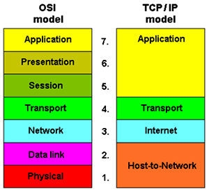
Host-to-Network Layer:
- The Host-to-Network layer interfaces the TCP/IP protocol stack to the physical network.
- The host has to connect to the network using some protocol so as to send or receive IP packets over it.
- Its job is to permit hosts to inject packets into any network and have they travel independently to the destination.
- It rearranges the data packets even if they won’t appear in order
- Defines official packet format and protocol called IP
- TCP/IP internet layer is similar in functionality to the OSI network layer
- Facilitates peer entities on the source and destination hosts to carry on a conversation.
- Transport layer is between Application layer and Internet layer
- Two end-to-end transport protocols have been defined here:
- Transmission Control Protocol -TCP : TCP is a reliable connection- oriented protocol that allows a byte stream originating on one machine to be delivered without error on any other machine in the internet.
- User Datagram Protocol- UDP : UDP is an unreliable, connectionless protocol for applications that do not want TCP's sequencing or flow control and wish to provide their own
- It contains all the higher-level protocols. The early ones included virtual terminal (TELNET), file transfer (FTP), and electronic mail (SMTP).
- The virtual terminal protocol allows a user on one machine to log onto a distant machine and work there
- Initially, electronic mail is a kind of file transfer which later was developed as specialized protocol (SMTP) for electronic mail.
| Layer | Description | Protocols |
| Application | Defines TCP/IP application protocols and how host programs interface with transport layer services to use the network. | HTTP, Telnet, FTP, TFTP, SNMP, DNS, SMTP, X Windows, other application protocols |
| Transport | Provides communication session management between host computers. Defines the level of service and status of the connection used when transporting data. | TCP, UDP, RTP |
| Internet | Packages data into IP datagram’s, which contain source and destination address information that is used to forward the datagram’s between hosts and across networks. Performs routing of IP datagram’s. | IP, ICMP, ARP, RARP |
| Network interface | Specifies details of how data is physically sent through the network, including how bits are electrically signaled by hardware devices that interface directly with a network medium, such as coaxial cable, optical fiber, or twisted-pair copper wire. | Ethernet, Token Ring, FDDI, X.25, Frame Relay, RS-232, v.35 |
Network Topologies:
Network topology is an array of various elements (links, nodes, etc.) of a computer network. To be defining, Network topology can be thought of as a schematic description of the arrangement of a network, including its nodes and connecting lines. There are two ways of defining network geometry:
- The physical topology
- The logical topology.
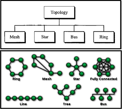
- Mesh:
In a mesh topology, every device has a dedicated point-to-point link to every other device. The term dedicated means that the link carries traffic only between the two devices it connects.
A. Partially connected
The type of network topology in which some of the nodes of the network are connected to more than one other node in the network with a point-to-point link – this makes it possible to take advantage of some of the redundancy that is provided by a physical fully connected mesh topology without the expense and complexity required for a connection between every node in the network
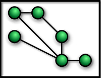
Partially connected mesh topology
B. Fully connected mesh topology
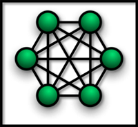
In this each of the nodes is connected to each other. In graph theory it known as a complete graph. A fully connected network doesn't need to use switching or broadcasting. However, its major disadvantage is that the number of connections grows quadratically with the number of nodes, as per the formula
c=n(n-1)/2 And so it is extremely impractical for large networks. A two-node network is technically a fully connected network.
- Star Topology:
Here each device has a dedicated point-to-point link only to a central controller, usually called a hub or switch. The switch is the server and the peripherals are the clients. The devices are not directly linked to one another. Unlike a mesh topology, a star topology does not allow direct traffic between devices. The controller acts as an exchange: If one device wants to send data to another, it sends the data to the controller, which then relays the data to the other connected device .
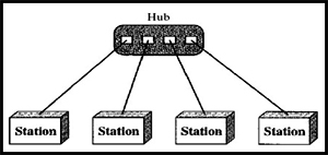
All traffic that traverses the network passes through the central hub. The hub acts as a signal repeater. The star topology is considered the easiest topology to design and implement. An advantage of the star topology is the simplicity of adding additional nodes.
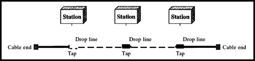
- Bus Topology:
Each computer or server is connected to the single bus cable. A signal from the source travels in both directions to all machines connected on the bus cable until it finds the intended recipient. If the machine address does not match the intended address for the data, the machine ignores the data. Alternatively, if the data matches the machine address, the data is accepted. Because the bus topology consists of only one wire, it is rather inexpensive to implement when compared to other topologies. Advantages of a bus topology include ease of installation. Backbone cable can be laid along the most efficient path, and then connected to the nodes by drop lines of various lengths.
- Ring topology:
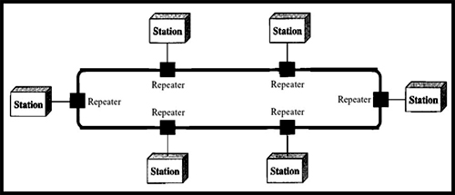
In a ring topology, each device has a dedicated point-to-point connection with only the two devices on either side of it. A signal is passed along the ring in one direction, from device to device, until it reaches its destination. Each device in the ring incorporates a repeater. When a device receives a signal intended for another device, its repeater regenerates the bits and passes them along.
Each device is linked to only its immediate neighbors (either physically or logically). To add or delete a device requires changing only two connections. The only constraints are media and traffic considerations (maximum ring length and number of devices).
1. Local Area Networks:
Local area networks, generally called LANs, are privately-owned networks within a single building or campus of up to a few kilo meters in size. They are widely used to connect personal computers and workstations in company offices and factories to share resources (e.g., printers) and exchange information. LANs are distinguished from other kinds of networks by three characteristics:
(1) Their size,
(2) Their transmission technology, and
(3) Their topology.
LANs are restricted in size, which means that the worst-case transmission time is bounded and known in advance. Knowing this bound makes it possible to use certain kinds of designs that would not otherwise be possible. It also simplifies network management. LANs may use a transmission technology consisting of a cable to which all the machines are attached, like the telephone company party lines once used in rural areas. Traditional LANs run at speeds of 10Mbps to 100 Mbps, have low delay (microseconds or nanoseconds), and make very few errors. Newer LANs operate at up to 10 Gbps various topologies are possible for broadcast LANs. Figure1 shows two of them. In a bus (i.e., a linear cable) network, at any instant at most one machine is the master and is allowed to transmit. All other machines are required to refrain from sending. An arbitration mechanism is needed to resolve conflicts when two or more machines want to transmit simultaneously. The arbitration mechanism may be centralized or distributed. IEEE 802.3, popularly called Ethernet, for example, is a bus-based broadcast network with decentralized control, usually operating at 10 Mbps to 10 Gbps. Computers on an Ethernet can transmit whenever they want to; if two or more packets collide, each computer just waits a random time and tries again later.
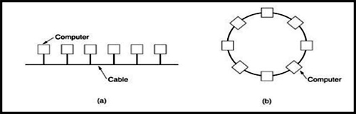
Fig.1: Two broadcast networks . (a) Bus. (b) Ring.
A second type of broadcast system is the ring. In a ring, each bit propagates around on its own, not waiting for the rest of the packet to which it belongs. Typically, each bit circumnavigates the entire ring in the time it takes to transmit a few bits, often before the complete packet has even been transmitted. As with all other broadcast systems, some rule is needed for arbitrating simultaneous accesses to the ring. Various methods, such as having the machines take turns, are in use. IEEE 802.5 (the IBM token ring), is a ring-based LAN operating at 4 and 16 Mbps. FDDI is another example of a ring network.
Metropolitan Area Network (MAN): Metropolitan Area Network:
A metropolitan area network, or MAN, covers a city. The best-known example of a MAN is the cable television network available in many cities. This system grew from earlier community antenna systems used in areas with poor over-the-air television reception. In these early systems, a large antenna was placed on top of a nearby hill and signal was then piped to the subscribers' houses. At first, these were locally-designed, ad hoc systems. Then companies began jumping into the business, getting contracts from city governments to wire up an entire city. The next step was television programming and even entire channels designed for cable only. Often these channels were highly specialized, such as all news, all sports, all cooking, all gardening, and so on. But from their inception until the late 1990s, they were intended for television reception only. To a first approximation, a MAN might look something like the system shown in Fig. In this figure both television signals and Internet are fed into the centralized head end for subsequent distribution to people's homes. Cable television is not the only MAN. Recent developments in high-speed wireless Internet access resulted in another MAN, which has been standardized as IEEE 802.16.
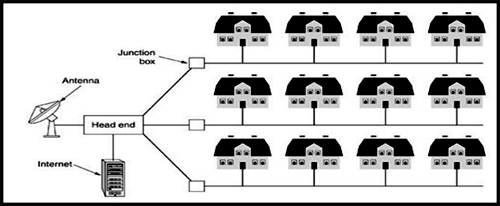
Fig.2: Metropolitan area network based on cable TV.
A MAN is implemented by a standard called DQDB (Distributed Queue Dual Bus) or IEEE 802.16. DQDB has two unidirectional buses (or cables) to which all the computers are attached.
Wide Area Network (WAN)
A wide area network, or WAN, spans a large geographical area, often a country or continent. It contains a collection of machines intended for running user (i.e., application) programs. These machines are called as hosts. The hosts are connected by a communication subnet, or just subnet for short. The hosts are owned by the customers (e.g., people's personal computers), whereas the communication subnet is typically owned and operated by a telephone company or Internet service provider. The job of the subnet is to carry messages from host to host, just as the telephone system carries words from speaker to listener.
Separation of the pure communication aspects of the network (the subnet) from the application aspects (the hosts), greatly simplifies the complete network design. In most wide area networks, the subnet consists of two distinct components: transmission lines and switching elements. Transmission lines move bits between machines. They can be made of copper wire, optical fiber, or even radio links. In most WANs, the network contains numerous transmission lines, each one connecting a pair of routers. If two routers that do not share a transmission line wish to communicate, they must do this indirectly, via other routers. When a packet is sent from one router to another via one or more intermediate routers, the packet is received at each intermediate router in its entirety, stored there until the required output line is free, and then forwarded. A subnet organized according to this principle is called a store-and-forward or packet-switched subnet. Nearly all wide area networks (except those using satellites) have store-and-forward subnets. When the packets are small and all the same size, they are often called cells.
The principle of a packet-switched WAN is so important. Generally, when a process on some host has a message to be sent to a process on some other host, the sending host first cuts the message into packets, each one bearing its number in the sequence. These packets are then injected into the network one at a time in quick succession. The packets are transported individually over the network and deposited at the receiving host, where they are reassembled into the original message and delivered to the receiving process. A stream of packets resulting from some initial message is illustrated in Fig. In this figure, all the packets follow the route ACE, rather than ABDE or ACDE. In some networks all packets from a given message must follow the same route; in others each packed is routed separately. Of course, if ACE is the best route, all packets may be sent along it, even if each packet is individually routed.
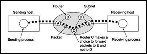
Fig.3.1: A stream of packets from sender to receiver.
Not all WANs are packet switched. A second possibility for a WAN is a satellite system. Each router has an antenna through which it can send and receive. All routers can hear the output from the satellite, and in some cases they can also hear the upward transmissions of their fellow routers to the satellite as well. Sometimes the routers are connected to a substantial point-to-point subnet, with only some of them having a satellite antenna. Satellite networks are inherently broadcast and are most useful when the broadcast property is important.