

Sakshi Education

Memory is central to the operation of a modern computer system. Memory is a large array of words or bytes, each with its own address.
A program resides on a disk as a binary executable file. The program must be brought into memory and placed within a process for it to be executed Depending on the memory management in use the process may be moved between disk and memory during its execution. The collection of processes on the disk that are waiting to be brought into memory for execution forms the input queue. i.e., select one of the processes in the input queue and to load that process into memory. We can provide protection by using two registers, usually a base and a limit. The base register holds the smallest legal physical memory address; the limit register specifies the size of the range. For example, if the base register holds 300040 and the limit register is 120900, then the program can legally access all addresses from 300040 through 420939(inclusive).
A base and limit register define a logical address space (Fig 1)
The binding of instructions and data to memory addresses can be done at any step along the way:
Compile time:
If it is known at compile time where the process will reside in memory, then absolute code can be generated.
Load time
If it is not known at compile time where the process will reside in memory, then the compiler must generate re-locatable code.
Execution time:
If the process can be moved during its execution from one memory segment to another, then binding must be delayed until run time.
Dynamic Loading:
Better memory-space utilization can be done by dynamic loading. With dynamic loading, a routine is not loaded until it is called. All routines are kept on disk in a re-locatable load format. The main program is loaded into memory and is executed. The advantage of dynamic loading is that an unused routine is never loaded.
Dynamic Linking:
Most operating systems support only static linking, in which system language libraries are treated like any other object module and are combined by the loader into the binary program image. The concept of dynamic linking is similar to that of dynamic loading. Rather than loading being postponed until execution time, linking is postponed. This feature is usually used with system libraries, such as language subroutine libraries. With dynamic linking, a stub is included in the image for each library-routine reference. This stub is a small piece of code that indicates how to locate the appropriate memory-resident library routing.
The entire program and data of a process must be in physical memory for the process to execute. The size of a process is limited to the size of physical memory. So that a process can be larger than the amount of memory allocated to it, a technique called overlays is sometimes used. The idea of overlays is to keep in memory only those instructions and data that are needed at any given time. When other instructions are needed, they are loaded into space that was occupied previously by instructions that are no longer needed.
Example, consider a two-pass assembler. During pass 1, it constructs a symbol table; then, during pass 2, it generates machine-language code. We may be able to partition such an assembler into pass 1 code, pass 2 code, the symbol table 1, and common support routines used by both pass 1 and pass 2.
Let us consider
Pass1 70K
Pass 2 80K
Symbol table 20K
Common routines 30K
To load everything at once, we would require 200K of memory. If only 150K is available, we cannot run our process. But pass 1 and pass 2 do not need to be in memory at the same time. We thus define two overlays: Overlay A is the symbol table, common routines, and pass 1, and overlay B is the symbol table, common routines, and pass 2. We add an overlay driver (10K) and start with overlay A in memory. When we finish pass 1, we jump to the overlay driver, which reads overlay B into memory, overwriting overlay A, and then transfers control to pass 2Overlay A needs only 120K, whereas overlay B needs 130K As in dynamic loading, overlays do not require any special support from the operating system.
Logical versus Physical Address Space:
An address generated by the CPU is commonly referred to as a logical address, whereas an address seen by the memory unit is commonly referred to as a physical address. The compile-time and load-time address-binding schemes result in an environment where the logical and physical addresses are the same. The execution-time address-binding scheme results in an environment where the logical and physical addresses differ. In this case, we usually refer to the logical address as a virtual address. The set of all logical addresses generated by a program is referred to as a logical address space; the set of all physical addresses corresponding to these logical addresses is referred to as a physical address space.
The run-time mapping from virtual to physical addresses is done by the memory management unit (MMU), which is a hardware device.
The base register is called a relocation register. The value in the relocation register is added to every address generated by a user process at the time it is sent to memory. For example, if the base is at 13000, then an attempt by the user to address location 0 dynamically relocated to location 14,000; an access to location 347 is mapped to location 13347. The MS-DOS operating system running on the Intel 80 x 86 families of processors uses four relocation registers when loading and running processes.
The user program never sees the real physical addresses. The program can create a pointer to location 347 store it memory, manipulate it, compare it to other addresses all as the number 347. The user program deals with logical addresses. The memory-mapping hardware converts logical addresses into physical addressed Logical addresses (in the range 0 to max) and physical addresses (in the range R + 0 to R + max for a base value R). The user generates only logical addresses.
The concept of a logical address space that is bound to a separate physical address space is central to proper memory management.
Swapping:
A process, can be swapped temporarily out of memory to a backing store, and then brought back into memory for continued execution. Assume a multiprogramming environment with a round robin CPU-scheduling algorithm. When a quantum expires, the memory manager will start to swap out the process that just finished, and to swap in another process to the memory space that has been freed when each process finishes its quantum, it will be swapped with another process.
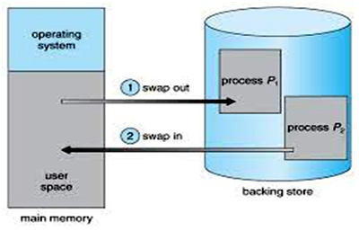
Fig 2: Memory Allocation
A variant of this swapping policy is used for priority-based scheduling algorithms (Fig 2). If a higher-priority process arrives and wants service, the memory manager can swap out the lower-priority process so that it can load and execute the higher priority process. When the higher priority process finishes, the lower-priority process can be swapped back in and continued. This variant of swapping is sometimes called rollout, roll in. A process is swapped out will be swapped back into the same memory space that it occupies previously. If binding is done at assembly or load time, then the process cannot be moved to different location. If execution-time binding is being used, then it is possible to swap a process into a different memory space.
Swapping requires a backing store. The backing store is commonly a fast disk. It is large enough to accommodate copies of all memory images for all users. The system maintains a ready queue consisting of all processes whose memory images are on the backing store or in memory and are ready to run.
The context-switch time in such a swapping system is fairly high. Let us assume that the user process is of size 100K and the backing store is a standard hard disk with transfer rate of 1 megabyte per second. The actual transfer of the
100K process to or from memory takes
100K / 1000K per second = 1/10 second
= 100 milliseconds
Contiguous Allocation:
The main memory must accommodate both the operating system and the various user processes. The memory is usually divided into two partitions, one for the resident operating system, and one for the user processes. To place the operating system in low memory. Thus, we shall discuss only me situation where the operating system resides in low memory. The development of the other situation is similar. Common Operating System is placed in low memory.
Single-Partition Allocation:
If the operating system is residing in low memory, and the user processes are executing in high memory. And operating-system code and data are protected from changes by the user processes. We also need protect the user processes from one another. We can provide this 2 protection by using relocation registers.
The relocation register contains the value of the smallest physical address; the limit register contains the range of logical addresses (for example, relocation = 100,040 and limit = 74,600). With relocation and limit registers, each logical address must be less than the limit register; the MMU maps the logical address dynamically by adding the value in the relocation register. This mapped address is sent to memory.
The relocation-register scheme provides an effective way to allow the operating system size to change dynamically.
Multiple-Partition Allocation:
One of the simplest schemes for memory allocation is to divide memory into a number of fixed-sized partitions. Each partition may contain exactly one process. Thus, the degree of multiprogramming is bound by the number of partitions. When a partition is free, a process is selected from the input queue and is loaded into the free partition. When the process terminates, the partition becomes available for another process.
The operating system keeps a table indicating which parts of memory are available and which are occupied. Initially, all memory is available for user processes, and is considered as one large block, of available memory, a hole. When a process arrives and needs memory, we search for a whole large enough for this process.
For example, assume that we have 2560K of memory available and a resident operating system of 400K. This situation leaves 2160K for user processes. FCFS job scheduling, we can immediately allocate memory to processes P1, P2, P3. Holes size 260K that cannot be used by any of the remaining processes in the input queue. Using a round-robin CPU-scheduling with a quantum of 1 time unit, process will terminate at time 14, releasing its memory. Memory allocation is done using Round-Robin Sequence as shown in fig. When a process arrives and needs memory, we search this set for a hole that is large enough for this process. If the hole is too large, it is split into two: One part is allocated to the arriving process; the other is returned to the set of holes. When a process terminates, it releases its block of memory, which is then placed back in the set of holes. If the new hole is adjacent to other holes, we merge these adjacent holes to form one larger hole.
This procedure is a particular instance of the general dynamic storage-allocation problem, which is how to satisfy a request of size n from a list of free holes. There are many solutions to this problem. The set of holes is searched to determine which hole is best to allocate, first-fit, best-fit, and worst-fit are the most common strategies used to select a free hole from the set of available holes.
First-fit: Allocate the first hole that is big enough. Searching can start either at the beginning of the set of holes or where the previous first-fit search ended. We can stop searching as soon as we find a free hole that is large enough.
Best-fit: Allocate the smallest hole that is big enough. We must search the entire list, unless the list is kept ordered by size. This strategy produces the smallest leftover hole.
Worst-fit: Allocate the largest hole. Again, we must search the entire list unless it is sorted by size. This strategy produces the largest leftover hole which may be more useful than the smaller leftover hole from a best-t approach
External and Internal Fragmentation
As processes are loaded and removed from memory, the free memory space is broken into little pieces. External fragmentation exists when enough to the memory space exists to satisfy a request, but it is not contiguous; storage is fragmented into a large number of small holes.
Depending on the total amount of memory storage and the average process size, external fragmentation may be either a minor or a major problem.
Given N allocated blocks, another 0.5N blocks will be lost due to fragmentation. That is, one-third of memory may be unusable. This property is known as the 50- percent rule. Internal fragmentation is memory that is internal to partition, but is not being used.
Paging:
External fragmentation is avoided by using paging. In this physical memory is broken into blocks of the same size called pages. When a process is to be executed, its pages are loaded into any available memory frames. Every address generated by the CPU is divided into any two parts: a page number(p) and a page offset(d) . The page number is used as an index into a page table. The page table contains the base address of each page in physical memory. This base address is combined with the gage offset to define the physical memory address that is sent to the memory unit.
Paging Hardware:
The page size like is defined by the hardware. The size of a page is typically a power of 2 varying between 512 bytes and 8192 bytes per page, depending on the computer architecture. The selection of a power of 2 as a page size makes the translation of a logical address into a page number and page offset. lf the size of logical address space is 2m, and a page size is 2n addressing units (bytes or words), then the high-order m - n bits of a logical address designate the page number, and the n low-order bits designate the page offset. Thus, the logical address is as follows:
Page number
Page offset
p d
m – n n
Where p is an index into the page table and d is the displacement within the page.
Paging is a form of dynamic relocation. Every logical address is bound by the paging hardware to some physical address.
When we use a paging scheme, we have no external fragmentation: Any free frame can be allocated to a process that needs it.
If process size is independent of page size, we can have internal fragmentation to average one-half page per process. When a process arrives in the system to be executed, its size, expressed in pages, is examined. Each page of the process needs one frame. Thus, if the process requires n pages, there must be at least n frames available in memory. If there are n frames available, they are allocated to this arriving process. The first page of the process is loaded into one of the allocated frames and the frame number is put in the page table for this process. The next page is loaded into another frame, and its frame number is put into the page table, and so on.
The user program views that memory as one single contiguous space, containing only this one program. But the user program is scattered throughout physical memory and logical addresses are translated into physical addresses. The operating system is managing physical memory, it must be aware of the allocation details of physical memory: which frames are allocated, which frames are available, how many total frames there are, and so on. This information is generally kept in a data structure called a frame table. The frame table has one entry for each physical page frame, indicating whether the latter is free allocated and, if it is allocated, to which page of which process or processes.
The operating system maintains a copy of the page table for each process. Paging therefore increases the context switch time.
Segmentation:
A user program can be subdivided using segmentation, in which the program and its associated data are divided into a number of segments. It is not required that all segments of all programs be of the same length, although there is a maximum segment length. As with paging, a logical address using segmentation consists of two parts, in this case a segment number and an offset.
Because of the use of unequal-size segments, segmentation is similar to dynamic partitioning. In segmentation, a program may occupy more than one partition, and these partitions need not be contiguous. Segmentation eliminates internal fragmentation but, like dynamic partitioning, it suffers from external fragmentation. However, because a process is broken up into a number of smaller pieces, the external fragmentation should be less. Whereas, paging is invisible to the programmer, segmentation is usually visible and is provided as a convenience for organizing programs and data.
Another consequence of unequal-size segments is that there is no simple relationship between logical addresses and physical addresses. Segmentation scheme would make use of a segment table for each process and a list of free blocks of main memory. Each segment table entry would have to as in paging give the starting address in main memory of the corresponding segment. The entry should also provide the length of the segment, to assure that invalid addresses are not used. When a process enters the Running state, the address of its segment table is loaded into a special register used by the memory management hardware.
Consider an address of n + m bits, where the leftmost n bits are the segment number and the rightmost m bits are the offset. The following steps are needed for address translation:
Extract the segment number as the leftmost n bits of the logical address.
Use the segment number as an index into the process segment table to find the starting physical address of the segment. Compare the offset, expressed in the rightmost m bits, to the length of the segment. If the offset is greater than or equal to the length, the address is invalid. The desired physical address is the sum of the starting physical address of the segment plus the offset. Segmentation and paging can be combined to have a good result.
Virtual Memory:
Virtual memory is a technique that allows the execution of process that may not be completely in memory. The main visible advantage of this scheme is that programs can be larger than physical memory
Virtual memory is the separation of user logical memory from physical memory this separation allows an extremely large virtual memory to be provided for programmers when only a smaller physical memory is available. Following are the situations, when entire program is not required to load fully.
A program resides on a disk as a binary executable file. The program must be brought into memory and placed within a process for it to be executed Depending on the memory management in use the process may be moved between disk and memory during its execution. The collection of processes on the disk that are waiting to be brought into memory for execution forms the input queue. i.e., select one of the processes in the input queue and to load that process into memory. We can provide protection by using two registers, usually a base and a limit. The base register holds the smallest legal physical memory address; the limit register specifies the size of the range. For example, if the base register holds 300040 and the limit register is 120900, then the program can legally access all addresses from 300040 through 420939(inclusive).
A base and limit register define a logical address space (Fig 1)
The binding of instructions and data to memory addresses can be done at any step along the way:
Compile time:
If it is known at compile time where the process will reside in memory, then absolute code can be generated.
Load time
If it is not known at compile time where the process will reside in memory, then the compiler must generate re-locatable code.
Execution time:
If the process can be moved during its execution from one memory segment to another, then binding must be delayed until run time.
Dynamic Loading:
Better memory-space utilization can be done by dynamic loading. With dynamic loading, a routine is not loaded until it is called. All routines are kept on disk in a re-locatable load format. The main program is loaded into memory and is executed. The advantage of dynamic loading is that an unused routine is never loaded.
Dynamic Linking:
Most operating systems support only static linking, in which system language libraries are treated like any other object module and are combined by the loader into the binary program image. The concept of dynamic linking is similar to that of dynamic loading. Rather than loading being postponed until execution time, linking is postponed. This feature is usually used with system libraries, such as language subroutine libraries. With dynamic linking, a stub is included in the image for each library-routine reference. This stub is a small piece of code that indicates how to locate the appropriate memory-resident library routing.
The entire program and data of a process must be in physical memory for the process to execute. The size of a process is limited to the size of physical memory. So that a process can be larger than the amount of memory allocated to it, a technique called overlays is sometimes used. The idea of overlays is to keep in memory only those instructions and data that are needed at any given time. When other instructions are needed, they are loaded into space that was occupied previously by instructions that are no longer needed.
Example, consider a two-pass assembler. During pass 1, it constructs a symbol table; then, during pass 2, it generates machine-language code. We may be able to partition such an assembler into pass 1 code, pass 2 code, the symbol table 1, and common support routines used by both pass 1 and pass 2.
Let us consider
Pass1 70K
Pass 2 80K
Symbol table 20K
Common routines 30K
To load everything at once, we would require 200K of memory. If only 150K is available, we cannot run our process. But pass 1 and pass 2 do not need to be in memory at the same time. We thus define two overlays: Overlay A is the symbol table, common routines, and pass 1, and overlay B is the symbol table, common routines, and pass 2. We add an overlay driver (10K) and start with overlay A in memory. When we finish pass 1, we jump to the overlay driver, which reads overlay B into memory, overwriting overlay A, and then transfers control to pass 2Overlay A needs only 120K, whereas overlay B needs 130K As in dynamic loading, overlays do not require any special support from the operating system.
Logical versus Physical Address Space:
An address generated by the CPU is commonly referred to as a logical address, whereas an address seen by the memory unit is commonly referred to as a physical address. The compile-time and load-time address-binding schemes result in an environment where the logical and physical addresses are the same. The execution-time address-binding scheme results in an environment where the logical and physical addresses differ. In this case, we usually refer to the logical address as a virtual address. The set of all logical addresses generated by a program is referred to as a logical address space; the set of all physical addresses corresponding to these logical addresses is referred to as a physical address space.
The run-time mapping from virtual to physical addresses is done by the memory management unit (MMU), which is a hardware device.
The base register is called a relocation register. The value in the relocation register is added to every address generated by a user process at the time it is sent to memory. For example, if the base is at 13000, then an attempt by the user to address location 0 dynamically relocated to location 14,000; an access to location 347 is mapped to location 13347. The MS-DOS operating system running on the Intel 80 x 86 families of processors uses four relocation registers when loading and running processes.
The user program never sees the real physical addresses. The program can create a pointer to location 347 store it memory, manipulate it, compare it to other addresses all as the number 347. The user program deals with logical addresses. The memory-mapping hardware converts logical addresses into physical addressed Logical addresses (in the range 0 to max) and physical addresses (in the range R + 0 to R + max for a base value R). The user generates only logical addresses.
The concept of a logical address space that is bound to a separate physical address space is central to proper memory management.
Swapping:
A process, can be swapped temporarily out of memory to a backing store, and then brought back into memory for continued execution. Assume a multiprogramming environment with a round robin CPU-scheduling algorithm. When a quantum expires, the memory manager will start to swap out the process that just finished, and to swap in another process to the memory space that has been freed when each process finishes its quantum, it will be swapped with another process.
Fig 2: Memory Allocation
A variant of this swapping policy is used for priority-based scheduling algorithms (Fig 2). If a higher-priority process arrives and wants service, the memory manager can swap out the lower-priority process so that it can load and execute the higher priority process. When the higher priority process finishes, the lower-priority process can be swapped back in and continued. This variant of swapping is sometimes called rollout, roll in. A process is swapped out will be swapped back into the same memory space that it occupies previously. If binding is done at assembly or load time, then the process cannot be moved to different location. If execution-time binding is being used, then it is possible to swap a process into a different memory space.
Swapping requires a backing store. The backing store is commonly a fast disk. It is large enough to accommodate copies of all memory images for all users. The system maintains a ready queue consisting of all processes whose memory images are on the backing store or in memory and are ready to run.
The context-switch time in such a swapping system is fairly high. Let us assume that the user process is of size 100K and the backing store is a standard hard disk with transfer rate of 1 megabyte per second. The actual transfer of the
100K process to or from memory takes
100K / 1000K per second = 1/10 second
= 100 milliseconds
Contiguous Allocation:
The main memory must accommodate both the operating system and the various user processes. The memory is usually divided into two partitions, one for the resident operating system, and one for the user processes. To place the operating system in low memory. Thus, we shall discuss only me situation where the operating system resides in low memory. The development of the other situation is similar. Common Operating System is placed in low memory.
Single-Partition Allocation:
If the operating system is residing in low memory, and the user processes are executing in high memory. And operating-system code and data are protected from changes by the user processes. We also need protect the user processes from one another. We can provide this 2 protection by using relocation registers.
The relocation register contains the value of the smallest physical address; the limit register contains the range of logical addresses (for example, relocation = 100,040 and limit = 74,600). With relocation and limit registers, each logical address must be less than the limit register; the MMU maps the logical address dynamically by adding the value in the relocation register. This mapped address is sent to memory.
The relocation-register scheme provides an effective way to allow the operating system size to change dynamically.
Multiple-Partition Allocation:
One of the simplest schemes for memory allocation is to divide memory into a number of fixed-sized partitions. Each partition may contain exactly one process. Thus, the degree of multiprogramming is bound by the number of partitions. When a partition is free, a process is selected from the input queue and is loaded into the free partition. When the process terminates, the partition becomes available for another process.
The operating system keeps a table indicating which parts of memory are available and which are occupied. Initially, all memory is available for user processes, and is considered as one large block, of available memory, a hole. When a process arrives and needs memory, we search for a whole large enough for this process.
For example, assume that we have 2560K of memory available and a resident operating system of 400K. This situation leaves 2160K for user processes. FCFS job scheduling, we can immediately allocate memory to processes P1, P2, P3. Holes size 260K that cannot be used by any of the remaining processes in the input queue. Using a round-robin CPU-scheduling with a quantum of 1 time unit, process will terminate at time 14, releasing its memory. Memory allocation is done using Round-Robin Sequence as shown in fig. When a process arrives and needs memory, we search this set for a hole that is large enough for this process. If the hole is too large, it is split into two: One part is allocated to the arriving process; the other is returned to the set of holes. When a process terminates, it releases its block of memory, which is then placed back in the set of holes. If the new hole is adjacent to other holes, we merge these adjacent holes to form one larger hole.
This procedure is a particular instance of the general dynamic storage-allocation problem, which is how to satisfy a request of size n from a list of free holes. There are many solutions to this problem. The set of holes is searched to determine which hole is best to allocate, first-fit, best-fit, and worst-fit are the most common strategies used to select a free hole from the set of available holes.
First-fit: Allocate the first hole that is big enough. Searching can start either at the beginning of the set of holes or where the previous first-fit search ended. We can stop searching as soon as we find a free hole that is large enough.
Best-fit: Allocate the smallest hole that is big enough. We must search the entire list, unless the list is kept ordered by size. This strategy produces the smallest leftover hole.
Worst-fit: Allocate the largest hole. Again, we must search the entire list unless it is sorted by size. This strategy produces the largest leftover hole which may be more useful than the smaller leftover hole from a best-t approach
External and Internal Fragmentation
As processes are loaded and removed from memory, the free memory space is broken into little pieces. External fragmentation exists when enough to the memory space exists to satisfy a request, but it is not contiguous; storage is fragmented into a large number of small holes.
Depending on the total amount of memory storage and the average process size, external fragmentation may be either a minor or a major problem.
Given N allocated blocks, another 0.5N blocks will be lost due to fragmentation. That is, one-third of memory may be unusable. This property is known as the 50- percent rule. Internal fragmentation is memory that is internal to partition, but is not being used.
Paging:
External fragmentation is avoided by using paging. In this physical memory is broken into blocks of the same size called pages. When a process is to be executed, its pages are loaded into any available memory frames. Every address generated by the CPU is divided into any two parts: a page number(p) and a page offset(d) . The page number is used as an index into a page table. The page table contains the base address of each page in physical memory. This base address is combined with the gage offset to define the physical memory address that is sent to the memory unit.
Paging Hardware:
The page size like is defined by the hardware. The size of a page is typically a power of 2 varying between 512 bytes and 8192 bytes per page, depending on the computer architecture. The selection of a power of 2 as a page size makes the translation of a logical address into a page number and page offset. lf the size of logical address space is 2m, and a page size is 2n addressing units (bytes or words), then the high-order m - n bits of a logical address designate the page number, and the n low-order bits designate the page offset. Thus, the logical address is as follows:
Page number
Page offset
p d
m – n n
Where p is an index into the page table and d is the displacement within the page.
Paging is a form of dynamic relocation. Every logical address is bound by the paging hardware to some physical address.
When we use a paging scheme, we have no external fragmentation: Any free frame can be allocated to a process that needs it.
If process size is independent of page size, we can have internal fragmentation to average one-half page per process. When a process arrives in the system to be executed, its size, expressed in pages, is examined. Each page of the process needs one frame. Thus, if the process requires n pages, there must be at least n frames available in memory. If there are n frames available, they are allocated to this arriving process. The first page of the process is loaded into one of the allocated frames and the frame number is put in the page table for this process. The next page is loaded into another frame, and its frame number is put into the page table, and so on.
The user program views that memory as one single contiguous space, containing only this one program. But the user program is scattered throughout physical memory and logical addresses are translated into physical addresses. The operating system is managing physical memory, it must be aware of the allocation details of physical memory: which frames are allocated, which frames are available, how many total frames there are, and so on. This information is generally kept in a data structure called a frame table. The frame table has one entry for each physical page frame, indicating whether the latter is free allocated and, if it is allocated, to which page of which process or processes.
The operating system maintains a copy of the page table for each process. Paging therefore increases the context switch time.
Segmentation:
A user program can be subdivided using segmentation, in which the program and its associated data are divided into a number of segments. It is not required that all segments of all programs be of the same length, although there is a maximum segment length. As with paging, a logical address using segmentation consists of two parts, in this case a segment number and an offset.
Because of the use of unequal-size segments, segmentation is similar to dynamic partitioning. In segmentation, a program may occupy more than one partition, and these partitions need not be contiguous. Segmentation eliminates internal fragmentation but, like dynamic partitioning, it suffers from external fragmentation. However, because a process is broken up into a number of smaller pieces, the external fragmentation should be less. Whereas, paging is invisible to the programmer, segmentation is usually visible and is provided as a convenience for organizing programs and data.
Another consequence of unequal-size segments is that there is no simple relationship between logical addresses and physical addresses. Segmentation scheme would make use of a segment table for each process and a list of free blocks of main memory. Each segment table entry would have to as in paging give the starting address in main memory of the corresponding segment. The entry should also provide the length of the segment, to assure that invalid addresses are not used. When a process enters the Running state, the address of its segment table is loaded into a special register used by the memory management hardware.
Consider an address of n + m bits, where the leftmost n bits are the segment number and the rightmost m bits are the offset. The following steps are needed for address translation:
Extract the segment number as the leftmost n bits of the logical address.
Use the segment number as an index into the process segment table to find the starting physical address of the segment. Compare the offset, expressed in the rightmost m bits, to the length of the segment. If the offset is greater than or equal to the length, the address is invalid. The desired physical address is the sum of the starting physical address of the segment plus the offset. Segmentation and paging can be combined to have a good result.
Virtual Memory:
Virtual memory is a technique that allows the execution of process that may not be completely in memory. The main visible advantage of this scheme is that programs can be larger than physical memory
Virtual memory is the separation of user logical memory from physical memory this separation allows an extremely large virtual memory to be provided for programmers when only a smaller physical memory is available. Following are the situations, when entire program is not required to load fully.
- User written error handling routines are used only when an error occurs in the data or computation.
- Certain options and features of a program may be used rarely.
- Many tables are assigned a fixed amount of address space even though only a small amount of the table is actually used.
The ability to execute a program that is only partially in memory would counter many benefits.
- Less number of I/O would be needed to load or swap each user program into memory.
- A program would no longer be constrained by the amount of physical memory that is available.
- Each user program could take less physical memory; more programs could be run the same time, with a corresponding increase in CPU utilization and throughput.
Demand Paging:
A demand paging is similar to a paging system with swapping. When we want to execute a process, we swap it into memory. Rather than swapping the entire process into memory.
When a process is to be swapped in, the pager guesses which pages will be used before the process is swapped out again Instead of swapping in a whole process; the pager brings only those necessary pages into memory. Thus, it avoids reading into memory pages that will not be used in anyway, decreasing the swap time and the amount of physical memory needed
Hardware support is required to distinguish between those pages that are in memory and those pages that are on the disk using the valid-invalid bit scheme. Where valid and invalid pages can be checked checking the bit and marking a page will have no effect if the process never attempts to access the pages. While the process executes and accesses pages that are memory resident, execution proceeds normally.
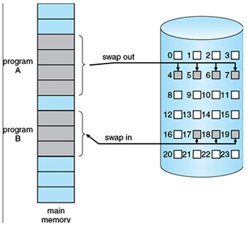
Fig 3: Demand Paging
Advantages of Demand Paging:
- Large virtual memory.
- More efficient use of memory.
- Unconstrained multiprogramming. There is no limit on degree of multiprogramming.
Disadvantages of Demand Paging:
- Number of tables and amount of processor over head for handling page interrupts are greater than in the case of the simple paged management techniques.
- Due to the lack of explicit constraints on a job address space size.
Page Replacement Algorithm:
There are many different page replacement algorithms. We evaluate an algorithm by running it on a particular string of memory reference and computing the number of page faults. The string of memory references is called reference string. Reference strings are generated artificially or by tracing a given system and recording the address of each memory reference. The latter choice produces a large number of data.
- For a given page size, we need to consider only the page number, not the entire address.
- If we have a reference to a page p, then any immediately following references to page p will never cause a page fault. Page p will be in memory after the first reference; the immediately following references will not fault.
E.g.: consider the address sequence
0100, 0432, 0101, 0612, 0102, 0103, 0104, 0101, 0611, 0102, 0103, 0104, 0101, 0610, 0102, 0103, 0104, 0104, 0101, 0609, 0102, 0105 and reduce to 1, 4, 1, 6,1, 6, 1, 6, 1, 6, 1.
To determine the number of page faults for a particular reference string and page replacement algorithm, we also need to know the number of page frames available. As the number of frames available increase, the number of page faults will decrease.
FIFO Algorithm:
The simplest page-replacement algorithm is a FIFO algorithm. A FIFO replacement algorithm associates with each page the time when that page was brought into memory. When a page must be replaced, the oldest page is chosen. We can create a FIFO queue to hold all pages in memory.
The first three references (7, 0, 1) cause page faults, and are brought into these empty e.g. 7, 0, 1, 2, 0, 3, 0, 4, 2, 3, 0, 3, 2, 1, 2, 0, 1 and consider 3 frames. This replacement means that the next reference to 0 will fault. Page 1 is then replaced by page 0.
Optimal Algorithm:
An optimal page-replacement algorithm has the lowest page-fault rate of all algorithms. An optimal page-replacement algorithm exists, and has been called OPT or MIN. It is simply replace the page that will not be used for the longest period of time.
Now consider the same string with 3 empty frames. The reference to page 2 replaces page 7, because 7 will not be used until reference 18, whereas page 0 will be used at 5, and page 1 at 14. The reference to page 3 replaces page 1, as page 1 will be the last of the three pages in memory to be referenced again. Optimal replacement is much better than a FIFO.
The optimal page-replacement algorithm is difficult to implement, because it requires future knowledge of the reference string.
LRU Algorithm:
The FIFO algorithm uses the time when a page was brought into memory; the OPT algorithm uses the time when a page is to be used. In LRU replace the Page that has not been used for the longest period of time.
LRU replacement associates with each page the time of that page's last use. When a page must be replaced, LRU chooses that page that has not been used for the longest period of time.
Let SR be the reverse of a reference string S, then the page-fault rate for the OPT algorithm on S is the same as the page-fault rate for the OPT algorithm on SR.
LRU Approximation Algorithms:
Some systems provide no hardware support, and other page-replacement algorithm. Many systems provide some help, however, in the form of a reference bit. The reference bit for a page is set, by the hardware, whenever that page is referenced. Reference bits are associated with each entry in the page table initially, all bits are cleared (to 0) by the operating system. As a user process executes, the bit associated with each page referenced is set (to 1) by the hardware.
Additional-Reference-Bits Algorithm:
The operating system shifts the reference bit for each page into the high-order or of its 8-bit byte, shifting the other bits right 1 bit, discarding the low-order bit.
These 8-bit shift registers contain the history of page use for the last eight time periods. If the shift register contains 00000000, then the page has not been used for eight time periods; a page that is used at least once each period would have a shift register value of 11111111.
Published date : 12 Dec 2015 11:46AM