

Sakshi Education
Overview of Mass-storage structure:
Disk Structure:
Fig: Disk Attachment
Swap- Space Management:
RAID Structure:
Stable-Storage Implementation:
Tertiary Storage Structure:
- Magnetic disks provide bulk of secondary storage of modern computers. Drives rotate at 60 to 200 times per second.
- Transfer rate is the rate at which data flow between drive and computer.
- Positioning time (random-access time) is time to move disk arm to desired cylinder (seek time) and time for desired sector to rotate under the disk head (rotational latency).
- Head crash results from disk head making contact with the disk surface. Disks can be removable.
- Disk drives are addressed as large 1-dimensional arrays of logical blocks, where the logical block is the smallest unit of transfer.
- The 1-dimensional array of logical blocks is mapped into the sectors of the disk sequentially. Sector 0 is the first sector of the first track on the outermost cylinder.
- Mapping proceeds in order through that track, then the rest of the tracks in that cylinder and then through the rest of the cylinders from outermost to innermost.
- The operating system is responsible for using hardware efficiently. For the disk drives, this means having a fast access time & disk bandwidth.
- Access time has two major components:
- Seek time is the time for the disk to move the heads to the cylinder containing the desired sector.
- Rotational latency is the time waiting for the disk to rotate the desired sector to the disk head. We like to minimize seek time.
- Disk bandwidth is the total number of bytes transferred divided by the total time between the first request for service and the completion of the last transfer.
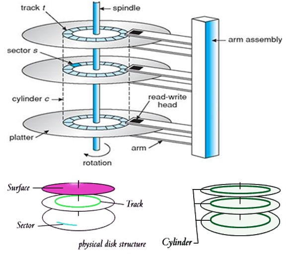
Disk Structure:
- The actual physical details of a modern hard disk may be quite complicated. Simply, there are one or more surfaces, each of which contains several tracks, each of which is divided into sectors.
- There is one read/ write head for every surface of the disk. Also, the same track on all surfaces is knows as a 'cylinder'. When talking about movement of the read/ write head, the cylinder is a useful concept, because all the heads (one for each surface), move in and out of the disk together.
- We say that the "read/ write head is at cylinder #2", when we mean that the top read-write head is at track #2 of the top surface, the next head is at track #2 of the next surface, the third head is at track #2 of the third surface, etc.
- The unit of information transfer is the sector (though often whole tracks may be read and written, depending on the hardware).
- As far as most filesystems are concerned, though, the sectors are what matter. In fact we usually talk about a 'block device'. A block often corresponds to a sector, though it need not do: several sectors may be aggregated to form a single logical block.
Fig: Disk Structure
- Disk drives are addressed as large 1-dimensional arrays of logical blocks, where the logical block is the smallest unit of transfer.
- The 1-dimensional array of logical blocks is mapped into the sectors of the disk sequentially.
- Sector 0 is the first sector of the first track on the outermost cylinder.
- Mapping proceeds in order through that track, then the rest of the tracks in that cylinder, and then through the rest of the cylinders from outermost to innermost.
Fig: Disk Attachment
Fig: Disk Scheduling
Swap- Space Management:
- Swap space in Linux is used when the amount of physical memory (RAM) is full. If the system needs more memory resources and the RAM is full, inactive pages in memory are moved to the swap space.
- While swap space can help machines with a small amount of RAM, it should not be considered a replacement for more RAM.
- Swap space is located on hard drives, which have a slower access time than physical memory.
- Swap space can be a dedicated swap partition (recommended), a swap file, or a combination of swap partitions and swap files.
- Swap should equal 2x physical RAM for up to 2 GB of physical RAM, and then an additional 1x physical RAM for any amount above 2 GB, but never less than 32 MB. So, if:
M = Amount of RAM in GB, and S = Amount of swap in GB, then
If M < 2
S = M *2
Else
S = M + 2 - Using this formula, a system with 2 GB of physical RAM would have 4 GB of swap, while one with 3 GB of physical RAM would have 5 GB of swap.
- Creating a large swap space partition can be especially helpful if you plan to upgrade your RAM at a later time.
- For systems with really large amounts of RAM (more than 32 GB) you can likely get away with a smaller swap partition (around 1x, or less, of physical RAM).
RAID Structure:
- RAID (redundant array of independent disks; originally redundant array of inexpensive disks) provides a way of storing the same data in different places (thus, redundantly) on multiple hard disks (though not all RAID levels provide redundancy).
- By placing data on multiple disks, input/output (I/O) operations can overlap in a balanced way, improving performance. Since multiple disks increase the mean time between failures (MTBF), storing data redundantly also increases fault tolerance.
- A single-user system where large records, such as medical or other scientific images, are stored, the stripes are typically set up to be small (perhaps 512 bytes) so that a single record spans all disks and can be accessed quickly by reading all disks at the same time.
- In a multi-user system, better performance requires establishing a stripe wide enough to hold the typical or maximum size record. This allows overlapped disk I/O across drives.
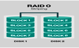
Fig: RAID Structure
Stable-Storage Implementation:
- Stable storage is a classification of computer data storage technology that guarantees atomicity for any given write operation and allows software to be written that is robustagainst some hardware and power failures.
- To be considered atomic, upon reading back a just written-to portion of the disk, the storage subsystem must return either the write data or the data that was on that portion of the disk before the write operation.
- Most computer disk drives are not considered stable storage because they do not guarantee atomic write; an error could be returned upon subsequent read of the disk where it was just written to in lieu of either the new or prior data.
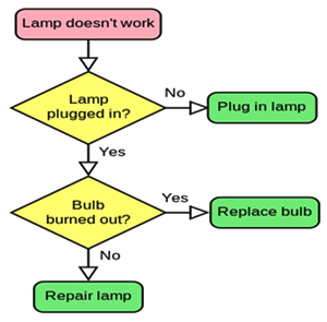
Fig: Stable-Storage Implementation Flowchart
Tertiary Storage Structure:
- Low cost is the defining characteristic of tertiary storage. Generally, tertiary storage is built using removable media. Common examples of removable media are floppy disks and CD-ROMs; other types are available.
- Floppy disk is thin flexible disk coated with magnetic material, enclosed in a protective plastic case. Most floppies hold about 1 MB; similar technology is used for removable disks that hold more than 1 GB.
- Removable magnetic disks can be nearly as fast as hard disks, but they are at a greater risk of damage from exposure.
- A magneto-optic disk records data on a rigid platter coated with magnetic material. – Laser heat is used to amplify a large, weak magnetic field to record a bit. – Laser light is also used to read data (Kerr effect).
- The magneto-optic head flies much farther from the disk surface than a magnetic disk head, and the magnetic material is covered with a protective layer of plastic or glass; resistant to head crashes.
- Optical disks do not use magnetism; they employ special materials that are altered by laser light.
Published date : 16 Feb 2016 05:34PM