Computer System Organization
Sakshi Education
Computer systems have become indispensable entities of today’s world.


Initially the need to reduce computational time and increase computational accuracy of the various mathematical and scientific problems was the need for its invention. This invention have revolutionized not computational field alone, instead it has revolutionized every field like offices, factories, hospitals, schools, stores, libraries, cars, your television , microwave. Apart from these we find their significant role in the key fields: science, engineering, medicine, business, government, education, entertainment, and many other areas.
In short Computers find their major role wherever there is demand for performing of complex and/or high speed tasks. In short a computer system can be defined as general purpose information processing machines used to solve problems. To understand in detail the design and working principles of the operating system, it is at most important to understand the principles governing the working of computer system, which involves the study of the computer organization.
Computer system operation:
The Two components are must in computer operation: Hardware and software. CPU, I/O controllers and Memory form the basic components of hardware, where as in software, BIOS, operating system, utility software and application software. These three form the basic unit of computer. To understand computer system operation we have to know in detail of characteristics of each of these components and how they function as a team to execute a task that computer is assigned.
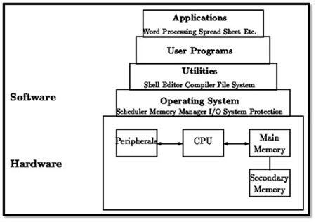
Fig: Modern Computer system operational hierarchy
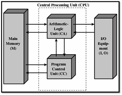
The Central processing unit (CPU) forms the core of the computer system. The Arithmetic Logic Unit (ALU) [performs arithmetic and logic operations, hardware registers that supply operands to the ALU and store the results], and the control unit [that fetches instructions from the main memory, and decodes and executes them while relying on the ALU] and registers form the basic functional units of CPU.
The processor takes the instruction from the device controllers, which are connected to various IO devices (like disk drives, audio devices, and video displays) and executes the task in sequence of instructions called as program. These instructions are stored in a computer memory and fetched while executing instruction. When one complete instruction is executed, then we say that one instruction cycle is completed. This process is completed guided by the operating system. In short instruction cycle happens in three steps: fetch, decode, and execute. This process is graphically demonstrated in the following figure:
To understand the computer operation cycle let’s consider, the start of a computer. When computer is switched on the first program that runs is bootstrap, which is a part of BIOS (Basic Input and Output Operating System) program which is stored in Read Only Memory (ROM). It initializes all aspects of the system, from CPU registers to device controllers to memory contents. Then bootstrap program loads the operating system and handover the control of the computer system to the operating system (OS). OS first runs the command INIT, this triggers an interrupt to the CPU, which is termed as system call. Then the CPU halts its current instruction by pushing the current status address of instruction execution in to interrupt vector (which holds the addresses of the various interrupts) table and then it shift to the new task, this task is handled by a routine named Interrupt Service Routine(ISR), which in turn would invoke interrupt handler . The address of the interrupted task is retrieved and completes the interrupt call and resumes its previous task from where it halted. Execution of INIT command gains the complete control of system to the operating system from BIOS.
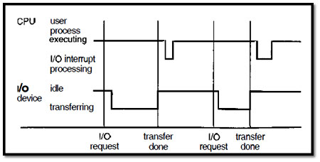
Figure: Interrupt time line for a single process doing output.
Storage Structure
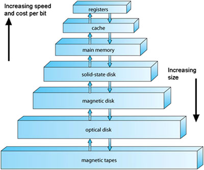
Memory is the place where data or programs are stored. Memory is of two types:
Main memory:
The computer programs that CPU fetches to execute an instruction are stored in Main Memory, which is also called as Random Access Memory (RAM). This is the only memory where processor can directly fetch data. When an operating system loads, the processor fetches the system related programs that are necessary to run the basic functions and stored in RAM, also when we request task the necessary instructions are brought and stored in RAM and then immediate instruction to be executed by the processor is brought from Ram to Cache memory.
The significance of this memory is that the processor needs not to follow sequence, it can fetch directly from which ever location it wants, and this is the reason why this memory is termed as Random Access Memory. The data in this memory get erased once the power is switched off, for this reason it is termed as volatile memory. Communication happens in a sequence of load or store instructions to a specific memory addresses. The load instruction moves data bytes from main memory to an internal register within the CPU, whereas the store instruction moves the content of a register to main memory.
Characteristics of Main Memory

Instruction Cycle
From the above figure,
Primary memory has cost, space and access time constraints. In order to overcome these challenges concept of secondary memory is introduced. These are non volatile in nature. Eg: Discs, tapes, USB’s, etc...
Characteristic of Secondary Memory
The most important constraint of a computer system is management of CPU time. In general purpose computers many IO devices are connected to system, because of which major share of CPU time is spent in data transfer i.e read and write an operation, this time goes beyond limit especially in case of devices that have less transfer rates, and thus CPU is fails to attend other tasks.
This process is completely relied on IO interrupt technique. Whenever the IO transfer request is made, an interrupt is raised by the controller and then the operating system loads the respective device driver program in to appropriate registers. The device controller up on examining the registers initiates the transfer operation from device to local buffer. Up on completion the device controller an interrupt will be raised to device controller and thus control will be handover to operating system. This technique stays valid in case of small packets of data transfer and fails in case of bulk data transfers.
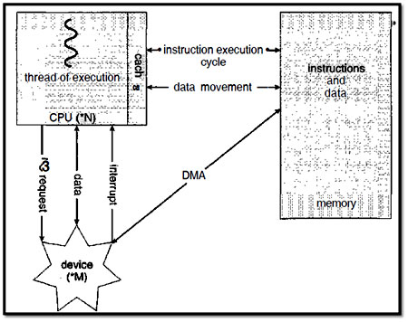
In order to solve this problem the concept of DIRECT MEMORY ACCESS (DMA) has been introduced. With DMA, the CPU initiates the transfer operation and handovers the control to the DMA controller and CPU heads with other task while the DMA takes carrying on the IO operation. The DMA operation is demonstrated in the figure below:
In short Computers find their major role wherever there is demand for performing of complex and/or high speed tasks. In short a computer system can be defined as general purpose information processing machines used to solve problems. To understand in detail the design and working principles of the operating system, it is at most important to understand the principles governing the working of computer system, which involves the study of the computer organization.
Computer system operation:
The Two components are must in computer operation: Hardware and software. CPU, I/O controllers and Memory form the basic components of hardware, where as in software, BIOS, operating system, utility software and application software. These three form the basic unit of computer. To understand computer system operation we have to know in detail of characteristics of each of these components and how they function as a team to execute a task that computer is assigned.

Fig: Modern Computer system operational hierarchy
The Central processing unit (CPU) forms the core of the computer system. The Arithmetic Logic Unit (ALU) [performs arithmetic and logic operations, hardware registers that supply operands to the ALU and store the results], and the control unit [that fetches instructions from the main memory, and decodes and executes them while relying on the ALU] and registers form the basic functional units of CPU.
The processor takes the instruction from the device controllers, which are connected to various IO devices (like disk drives, audio devices, and video displays) and executes the task in sequence of instructions called as program. These instructions are stored in a computer memory and fetched while executing instruction. When one complete instruction is executed, then we say that one instruction cycle is completed. This process is completed guided by the operating system. In short instruction cycle happens in three steps: fetch, decode, and execute. This process is graphically demonstrated in the following figure:

To understand the computer operation cycle let’s consider, the start of a computer. When computer is switched on the first program that runs is bootstrap, which is a part of BIOS (Basic Input and Output Operating System) program which is stored in Read Only Memory (ROM). It initializes all aspects of the system, from CPU registers to device controllers to memory contents. Then bootstrap program loads the operating system and handover the control of the computer system to the operating system (OS). OS first runs the command INIT, this triggers an interrupt to the CPU, which is termed as system call. Then the CPU halts its current instruction by pushing the current status address of instruction execution in to interrupt vector (which holds the addresses of the various interrupts) table and then it shift to the new task, this task is handled by a routine named Interrupt Service Routine(ISR), which in turn would invoke interrupt handler . The address of the interrupted task is retrieved and completes the interrupt call and resumes its previous task from where it halted. Execution of INIT command gains the complete control of system to the operating system from BIOS.

Figure: Interrupt time line for a single process doing output.
Storage Structure
Memory is the place where data or programs are stored. Memory is of two types:
- Main memory or primary memory
- Secondary memory

Main memory:
The computer programs that CPU fetches to execute an instruction are stored in Main Memory, which is also called as Random Access Memory (RAM). This is the only memory where processor can directly fetch data. When an operating system loads, the processor fetches the system related programs that are necessary to run the basic functions and stored in RAM, also when we request task the necessary instructions are brought and stored in RAM and then immediate instruction to be executed by the processor is brought from Ram to Cache memory.
The significance of this memory is that the processor needs not to follow sequence, it can fetch directly from which ever location it wants, and this is the reason why this memory is termed as Random Access Memory. The data in this memory get erased once the power is switched off, for this reason it is termed as volatile memory. Communication happens in a sequence of load or store instructions to a specific memory addresses. The load instruction moves data bytes from main memory to an internal register within the CPU, whereas the store instruction moves the content of a register to main memory.
Characteristics of Main Memory
- semiconductor memories
- Known as main memory.
- Usually volatile in nature
- Data is lost in case power is switched off.
- It is working memory of the computer.
- Faster than secondary memories.
- A computer cannot run without primary memory.
- First fetches an instruction from memory and stores that instruction in the instruction register.
- The instruction is then decoded and may cause operands to be fetched from memory and stored in some internal register.
- After the instruction on the operands has been executed, the result may be stored back in memory.

Instruction Cycle
From the above figure,
- Program counter (PC) holds address of the instruction to be fetched next,
- The processor fetches the instruction from memory,
- Program counter is incremented after each fetch,
- Overlapped on modern architectures (pipelining).
Primary memory has cost, space and access time constraints. In order to overcome these challenges concept of secondary memory is introduced. These are non volatile in nature. Eg: Discs, tapes, USB’s, etc...
Characteristic of Secondary Memory
- These are magnetic and optical memories
- It is known as backup memory.
- It is non-volatile memory.
- Data is permanently stored even if power is switched off.
- It is used for storage of data in a computer.
- Computer may run without secondary memory.
- Slower than primary memories.
The most important constraint of a computer system is management of CPU time. In general purpose computers many IO devices are connected to system, because of which major share of CPU time is spent in data transfer i.e read and write an operation, this time goes beyond limit especially in case of devices that have less transfer rates, and thus CPU is fails to attend other tasks.
This process is completely relied on IO interrupt technique. Whenever the IO transfer request is made, an interrupt is raised by the controller and then the operating system loads the respective device driver program in to appropriate registers. The device controller up on examining the registers initiates the transfer operation from device to local buffer. Up on completion the device controller an interrupt will be raised to device controller and thus control will be handover to operating system. This technique stays valid in case of small packets of data transfer and fails in case of bulk data transfers.
In order to solve this problem the concept of DIRECT MEMORY ACCESS (DMA) has been introduced. With DMA, the CPU initiates the transfer operation and handovers the control to the DMA controller and CPU heads with other task while the DMA takes carrying on the IO operation. The DMA operation is demonstrated in the figure below:

Published date : 27 Jan 2015 12:46PM


