

Sakshi Education
- Introduction:
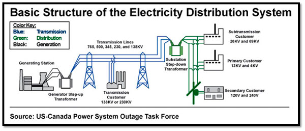
The conductor system by means of which the electrical energy is conveyed from bulk power sources to the consumer is known as distribution system. The distribution system may be divided into two systems as high voltage or primary distribution and low voltage or secondary distribution.
Figure: Electrical supply system
Primary Distribution System
From generating station the electrical power is usually transmitted to various substations through extra high tension transmission lines at voltage from 33 to 220kV. At this substation this voltage is steeped down to 11 or 6.6 or 3.3kV and power at this voltage is conveyed to different substation for the distribution and to the bulk supply consumers. Such a system is known as high voltage or primary distribution system. The voltage employed for primary distribution system depends upon the amount of power to be conveyed and the distances of the substations required fed.
Secondary Distribution System
At distribution substations voltage is steeped down to 400 volts. From these substations various low voltage distributors radiate out and feed the consumers. This system of distribution is known as low voltage or secondary distribution system. The distribution system may be sub divided into feeders, distributors and service mains.
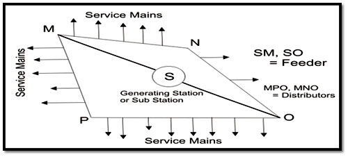
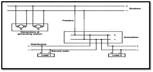
Figure: Elements of distribution system
Feeder:
Feeders are the conductors which connect the stations to the areas to be fed by those stations. Generally from feeder no tapping is taken to the consumers therefore, current loading of a feeder remains the same along its length. It designed mainly from the point of view current carrying capacity.
Distributors:
Distributors are conductors from which numerous tapping’s for the supply to the consumers are taken the current loading of a distributor various along its length. Distributors are designed from the point of view of the voltage drop.
Service Mains:
Service mains are the conductors, which connect the consumer’s terminals to the distributor.
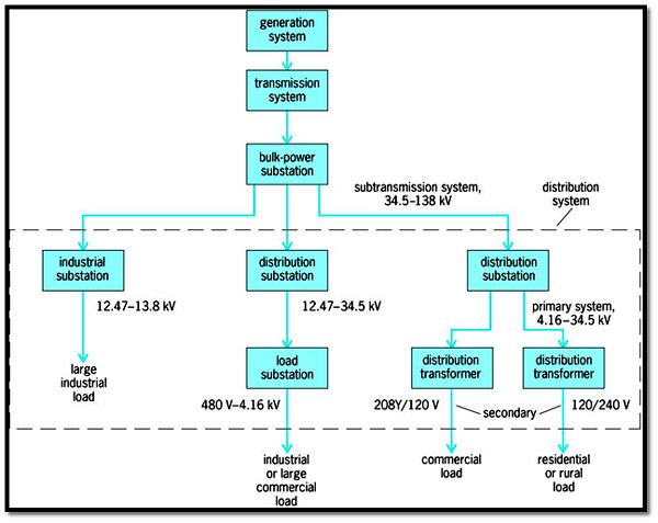
Fig: Overview of the power system from generation to consumer's switch.
- Classification of Distribution Systems:
Distribution systems may be classified in various ways:
According to the current the distribution system may be classified as
a) AC distribution
b) DC distribution
a) AC distribution:
In the AC power system, supply power is generated by 3-phase alternators operating in parallel at generating stations. The generation voltage is usually 11kV it may be 3.3, 6.6 or even 33kV in certain case this voltage is steeped up from 11kV to 220kV at the generating stations by means of 3-phase transformers.
The primary transmission lines transmit electrical power from the generating stations to primary transmission substations. At these primary substations the voltage is steeped down to 33kV by means of step-down transformer. From primary substation electrical power is transmitted through secondary transmission lines at 33kV to various secondary transmission substations at the secondary substation further steeped down to 11kV by means of 3-phase power supply is supplied from distribution substation through primary distribution lines at 11kV.
The distribution substations are located at suitable places in area in which power is to be supplied at these substations the voltage is steeped down to 415V the secondary distribution lines called distributors.
b) Dc distribution:
The conductor system by means of which electrical energy is conveyed from bulk power sources to the consumer is known as distribution system. The distribution system may be divided into two systems as high voltage or primary distribution and low voltage or secondary distribution.
Primary Distribution System from generating station the electrical power is usually transmitted to various substations through extra high tension transmission lines at voltage from 33 to 220kV. At this substation this voltage is steeped down to 11 or 6.6 or 3.3kV and power at this voltage is conveyed to different substation for the distribution and to the bulk supply consumers. Such a system is known as high voltage or primary distribution system.
The voltage employed for primary distribution system depends upon the amount of power to be conveyed and the distances of the substations required fed.
In case of Secondary Distribution System, at distribution substations voltage is steeped down to 400 volts. From these substations various low voltage distributors radiate out and feed the consumers. This system of distribution is known as low voltage or secondary distribution system.
According to character of service the distribution system may be classified as
a) General light and power
b) Industrial power
c) Railway
d) Street lighting
According to type of construction the distribution system may be classified as
a) Overhead distribution system
b) Underground distribution system
a) Overhead distribution system
In overhead system the conductors are insulated from x-arms and supporting towers and as the towers and x-arms are earthed so the maximum voltage between each conductor and earth forms the basis of comparison volume of conductor material required .
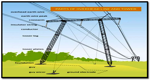
Figure: Overhead distribution system
b) Underground distribution system:
In underground system the maximum disruptive stress is between the two conductors of the cable so the maximum voltage between conductors forms the basis of comparison of volume of conductor material required.
.
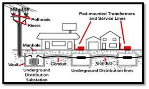
Figure: Underground distribution system
Due to low cost overhead this type system is usually employed. Underground distribution system is used where overhead systems become impracticable.
According to number of wires distribution system may be classified as
a) Two wire
b) Three wire
c) Four wire
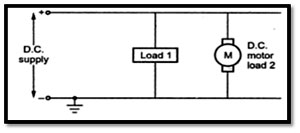
In a DC system, the electrical energy may be fed and distributed either by two wires or three wire system. In a 2-wire DC distribution system the energy is distributed from generating station or substations to the consumer terminals as shown in figure. Untapped feeders run to bus bars in suitable feeding points in to the distributor area and distributors’ cables are connected to the bus-bars through fuses or links which in turn run through the street lines premises that required supply. Each spate consumer is fed from distributor by a service cable tapped on to be distributor at the nearest convened point.
.
It consist of two wires ,one out going also known as positive wire, and another is returning one known as negative wire. In this system lamp, motors and other electrical appliances are connecting in parallel between the two wires.
.
This system is never employed for transmission purposes because of poor efficiency. In case of dc supply 3-wire distribution system is usually employed owing to its advantages over it
In case of AC supply, 3-phase 3-wire system is employed for balanced loads such as power loads. In 3-phase 4-wire system are employed unbalanced loads such as light and power loads.
According to the schema connection the distribution system may be classified as
a) Radial distribution system
b) Parallel distribution system
c) Ring distribution system
d) Interconnected distribution system
- The radial system is the simplest and lowest in terms of first cost, but poor in service reliability.
- The parallel system provides improved reliability of supply, particularly if the circuit flow in different routes
- The ring distribution system provides alternative supplies to a number of scattered substations.
- Comparison of DC vs. AC
Dc system:- It requires only two conductors for transmission and it is possible to transmit the power through only one conductor by using earth as returning conductor, hence much cooper is saved.
- There is no skin effect in dc cross-section of line conductor is fully utilized.
- A dc line has less corona loss and reduced interference with communication circuits.
- No stabilizer is required for transmission over long distances.
- Charging current which contributes to continuous loss even on no load is eliminated.
The only difficulty is of obtaining the necessary high voltage required for transmission as neither electrical power can be generated at high voltage because of communication difficult nor voltage be steeped up
- More copper is required.
- There is a skin effect in AC cross-section of line conductor is fully utilized.
- Ac line has more corona loss.
- The construction of transmission lines for Ac systems is not as easy as DC systems.
- The alternators are to be synchronized before putting them into parallel.
- The variation in speeds of alternators are to be controlled within very low limits
- There is a continuous loss on account of charging current even through line is open.
- Under-Ground vs. Over - Head Distribution Systems
Transmission and distribution of electrical power can be carried out by overhead as well as underground system.comparision between two as given below.
- Public Safety: Underground system is safer than overhead system.
- Initial Cost: Underground system is more expensive. For a particular amount of power to be transmitted at a given voltage the underground system costs almost double the cost of overhead.
- Flexibility: Overhead system is more flexible than Underground system.
- Working Voltage: The underground system cannot be operated above 66Kv because of insulation difficult. But overhead system can be designed for operation up to 400Kv.
- Maintenance Cost: Maintenance cost of Underground system is very low in comparison with Overhead system.
- Frequency of Accidents: The chances of accidents in Underground system are very low compared to Overhead system.
- Fault Location and repairs: Though there are very rare chance of occurring faults in Underground system, but if occurs very difficult to locate fault and repair is difficult and expensive.
- Jointing: Underground cables are difficult so tapping for loads and service mains is not conveniently possible in underground system.
- Damage due to lighting and thunder storm: Underground system is free from interruption of service on account of thunder storm lighting and object falling across the wire.
- Surge effect: In underground system surge effect is smoothed down as surge energy absorbed by the sheath.
- Requirements and Design features of Distribution Systems:
The necessary requirements of distribution system is
- The continuity in the power supply must ensure system reliability.
- The efficiency of the lines must be as high as possible.
- The system should be safe and no leakage from the consumer point of view.
- The lines should not be over load.
- The system should be economical.
Requirements of distribution system classified into three types
a) Proper voltage
b) Availability of power and demand
c) Reliability
Design Features of Distribution System:
The distribution system should be designed so as to be economical, but concerning to the Indian electricity rules it is essential to design with minimum volume of the conductor materials that are consistent with the voltage regulation needs.
Both voltage drop and current ratings in additional to overall economy are the important considerations in the design of distribution system. The cross sectional area feeder is determined on the basis of current to be carried and for overall economy. The consideration of voltage drop is not important in the design of feeder because no consumer is trapped off from it and the receiving end voltage can be raised to desired value and kept within the permissible limit.
The voltage regulation is very important in the design of distributor,because of the saturation regulation at the voltage variations permissible at the consumer terminals is -+6%.
- Voltage Drop Calculations (Numerical Problems) in D.C Distributors for the following cases:
a) Distributor fed one end:In this type of feeding, the distributor is connected to supply mains at one end and the loads are tapped at different points along the length of the distributors, as shown in figure below.
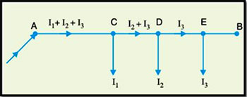
Consider a distributor AB with concentrated loads of I1, I2, and I3 at point C, D and E respectively and fed at one point as shown above figure. In this figure only for simplicity one wire is shown instead of two but resistances are for both wires for respective sections.
Total current fed from feeding point A=I1+I2+I3
The currents flowing through different sections are given below
| Sections | Current flowing |
| AC | I1+I2+I3 |
| CD | I2+I3 |
| DE | I3 |
Voltage drop in section AC= (I1+I2+I3) r1
Voltage drop in section CD= (I2+I3) r2
Voltage drop in section DE=I3r3
Total voltage drop in the distributor
= (I1+I2+I3) r1+ (I2+I3) r2+I3r3
From the above two equations it can be seen that current in the section is away from the feeding point and the voltage across the load point is away from the feeding point and goes on decreasing and the voltage is maximum across the furthest load point E.
b) At the both the ends (equal/unequal Voltages):
In this type of feeding, the distributor is connected to supply mains at the both ends as shown in figure. The voltage at both feeding points may be different or equal. In this type of distributor, load voltages first goes on decreasing reaches the minimum value and then start increasing reaching finally the maximum value. The point of minimum voltage is never fixed and always shifts with the variations of load on the different sections of the distributors.
Equal voltages:
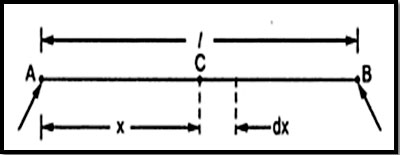
Let the distributor AB is of length l, resistances r ohms per unit run of both of the conductors loaded with i amperes per unit and the run be fed from the feeding points A and B at equal voltages of V volts as shown above figure.
Let us find the voltage drop in section AC, C begging a point at a distance of x units from feeding point A.
Total current on conductor AB=il
Current supplied from each end=il/2
The current at point C =
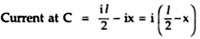
Consider a section of very small length dx near point C. its resistance is r dx, hence voltage drop in length dx is given by
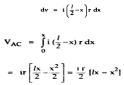
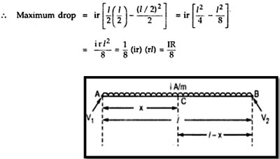
The maximum voltage drop will occur midpoint i.e when x=l/2
So maximum voltage drop,
Unequal voltages:
Let the distributor AB is of length l, resistances r ohms per unit run of both of the conductors loaded with i amperes per unit and the run be fed from the feeding points A and B at equal voltages of VA and VB volts as shown above figure.
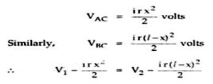
Let the point C is at distance of x-units from the feeding point A which is at a minimum voltage. So there will be no current at the point C and the current fed from feeding point A will be the current in section AC i.e.ix.
Hence voltage drops in section AC=ir x2/2 volts
Point C is also at a distance of(l-x)units from B so current fed by feeding point B is i(l-x) and voltage drop in section BC is ir(l-x)2/2 volts
Now voltage at point C =voltage at feeding point A-voltage drop in section AC also =voltage at feeding point B-voltage drop in section BC
c) Ring Main Distributor:
A distributor arranged to form a closed circuit and fed at one or more points is called the ring main distributor. The advantages of such an arrangement are greater reliability and better flexibility. In the event of fault in any section it can be isolated from both the sides and the continuity of supply is maintained for the reaming sections. The result is that only a faulty section suffers the discontinuity of supply. The ring distributor fed at one point for the purpose of calculations can be considered equivalent to a straight distributor fed from both ends at equal voltages. A ring main distribriutor as shown in figure.
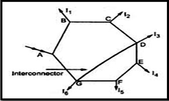
Sometimes two or more ends of a ring main are connected through interconnector so as to form a complete network. The addition of an interconnector to a ring main reduces the voltage drop and power loss in the system.
Published date : 28 Jan 2015 02:39PM