

Sakshi Education
Design Engineering is the topic that covers the set of principles, concepts, and practices that lead to the development of a high quality system or product. Goal of design engineering is to produce a model or representation that depicts:
The design model provides detail about software data structures, architecture, interfaces, and components that are necessary to implement the system. The process by which the design model is developed is described by Belady [BEL81]:
“There are two major phases to any design process: diversification and convergence. Diversification is the acquisition of a repertoire of alternatives, the raw material of design: components, component solutions, and knowledge, all contained in catalogs, textbooks, and the mind. During convergence, the designer chooses and combines appropriate elements from this repertoire to meet the design objectives, as stated in the requirements document and as agreed to by the customer. The second phase is the gradual elimination of all but one particular configuration of components, and thus the creation of the final product.”
Well structured definition about what is design can be heard in words of Roger pressmen in his book Software Engineering as:
“Design is a meaningful engineering representation of something that is to be built. It can be traced to a customer’s requirements and at the same time assessed for quality against a set of predefined criteria for “good” design. In the software engineering context, design focuses on four major areas of concern: data, architecture, interfaces, and components. The concepts and principles discussed in this chapter apply to all four.”
1.1 Software Design
Software design model consists of 4 designs:
Translating Analysis -> Design:
Translating Analysis to Design process involved following steps:
1.2 Software Design Process and Design Quality
Software(s/w) design is an iterative process through which requirements are translated into a “blueprint” for constructing the s/w. As design iteration occur, subsequent refinement leads to design representation at much lower levels of abstraction.
1.2.1 Goal of design process
Characteristics of good design
Design concepts
Design concepts provide the necessary framework for “to get the thing on right way”.
At the highest level of abstraction – a solution is stated in broad terms. At lower level of abstraction – a more detailed description of the solution is provided. Two types of abstraction:
I. Procedural abstraction: Sequence of instructions that have a specific and limited function.
Ex. Open a door
Open implies long sequence of activities (e.g. walk to the door, grasp knob, turn knob and pull the door, etc).
II. Data abstraction: collection of data that describes a data object.
Ex. Open a door. – door is data object.
2. Refinement
Refinement is actually a process of elaboration. It begins with a statement of function (or description of information) that is defined at a high level of abstraction. That is, the statement describes function or information conceptually but provides no information about the internal workings of the function or the internal structure of the information.
Refinement causes the designer to elaborate on the original statement, providing more and more detail as each successive refinement (elaboration) occurs. Abstraction and refinement are complementary concepts. Abstraction enables a designer to specify procedure and data and yet suppress low-level details. Refinement helps the designer to expose low-level details as design progresses.
3. Modularity
Architecture and design pattern embody modularity. Software is divided into separately named and addressable components, sometimes called modules, which are integrated to satisfy problem requirement. Modularity is the single attribute of software that allows a program to be intellectually manageable. It leads to a “divide and conquer” strategy, in which a complex problem when you break into a manageable pieces.
Refer fig. that state that effort (cost) to develop an individual software module does decrease if the total number of modules increases. However as the no. of modules grows, the effort (cost) associated with integrating the modules also grows.
Modularity and software cost
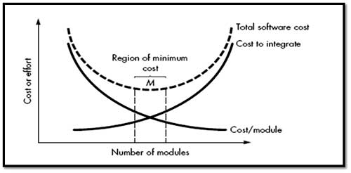
Undermodularity and overmodularity should be avoided. But how do we know the vicinity of M? We modularize a design so that development can be more easily planned. Software increments can be defined and delivered. Changes can be more easily accommodated. Testing and debugging can be conducted more efficiently and long-term maintained can be conducted without serious side effects.
4. Architecture
Software architecture suggests “the overall structure of the software and the ways in which that structure provides conceptual integrity for a system. No. of different models can use to represent architecture.
5. Control Hierarchy
Control hierarchy, represents the organization of program components (modules) and implies a hierarchy of control. Different notations are used to represent control hierarchy for those architectural styles that are amenable to this representation. The most common is the treelike diagram that represents hierarchical control for call and return architectures.
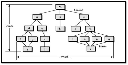
In fig. depth and width provide an indication of the number of levels of control and overall span of control. Fan-out is a measure of the number of modules that are directly controlled by another module. Fan-in indicates how many modules directly control a given module. A module that controls another module is said to be superordinate to it, and conversely, a module controlled by another is said to be subordinate to the controller.
Ex. Module M is superordinate to modules a, b, and c.
Module h is subordinate to module e
6. Structural Partitioning
II. Vertical Partitioning
Horizontal Partitioning:
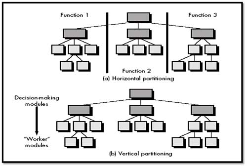
It defines separate branches of the modular hierarchy for each major program function. Control modules, represented in a darker shade are used to coordinate communication & execution between its functions. Horizontal partitioning defines three partitions—input, data transformation (often called processing) and output. Benefits of horizontal partitioning:
On the negative side (Drawback), horizontal partitioning often causes more data to be passed across module interfaces and can complicate the overall control of program flow.
Vertical Partitioning:
It is often referred as factoring. This suggests that control (decision making) and work should be distributed top-down in the program structure. Top-level modules should perform control functions and do little actual processing work. Modules that reside low in the structure should be the workers, performing all input, computation, and output tasks.
A change in a control module (high in the structure) will have a higher probability of propagating side effects to modules that are subordinate to it. A change to a worker module, given its low level in the structure, is less likely to cause the propagation of side effects. For this reason vertically partitioned structures are less likely to be susceptible to side effects when changes are made and will therefore be more maintainable.
7. Data Structure
Data structure is a representation of the logical relationship among individual elements of data.
A scalar item is the simplest of all data structures. It represents a single element of information that may be addressed by an identifier. When scalar items are organized as a list or contiguous group, a sequential vector is formed. When the sequential vector is extended to two, three, and ultimately, an arbitrary number of dimensions, an n-dimensional space is created. Most common n-dimensional space is the two-dimensional matrix
A linked list is a data structure that organizes contiguous scalar items, vectors, or spaces in a manner (called nodes) that enables them to be processed as a list.
A hierarchical data structure is implemented using multilinked lists that contain scalar items, vectors, and possibly, n-dimensional spaces.
Software Procedure
Software procedure focuses on the processing details of each module individually. Procedure must provide a precise specification of processing, including sequence of events, exact decision points, repetitive operations, and even data organization and structure.
8. Information Hiding
The principle of information hiding suggests that modules be "characterized by design decisions that (each) hides from all others modules.“ In other words, modules should be specified and designed so that information (algorithm and data) contained within a module is inaccessible to other modules that have no need for such information.
The intent of information hiding is to hide the details of data structure and procedural processing behind a module interface. It gives benefits when modifications are required during testing and maintenance because data and procedure are hiding from other parts of software, unintentional errors introduced during modification are less.
Effective Modular Design
Functional Independence
Functional independence is achieved by developing modules with "single-minded“function and an "aversion" to excessive interaction with other modules. In other words - each module addresses a specific sub-function of requirements and has a simple interface when viewed from other parts of the program structure. Independence is important –
Cohesion is a natural extension of the information hiding concept. A cohesive module performs a single task within a software procedure, requiring little interaction with procedures being performed in other parts of a program. Simply state, a cohesive module should (ideally) do just one thing.
We always strive for high cohesion, although the mid-range of the spectrum is often acceptable. Low-end cohesiveness is much "worse" than middle range, which is nearly as "good" as high-end cohesion. So, designer should avoid low levels of cohesion when modules are designed. When processing elements of a module are related and must be executed in a specific order, procedural cohesion exists.
When all processing elements concentrate on one area of a data structure, communicational cohesion is present. High cohesion is characterized by a module that performs one distinct procedural task.
Types of cohesion
As an example of low cohesion, consider a module that performs error processing for an engineering analysis package. The module is called when computed data exceed pre-specified bounds. It performs the following tasks:
(1) computes supplementary data based on original computed data,
(2) Produces an error report (with graphical content) on the user's workstation,
(3) Performs follow-up calculations requested by the user,
(4) Updates a database, and
(5) Enables menu selection for subsequent processing.
Although the preceding tasks are loosely related, each is an independent functional entity that might best be performed as a separate module. Combining the functions into a single module can serve only to increase the likelihood of error propagation when a modification is made to one of its processing tasks.
Coupling
The coupling depends on the interface complexity between modules, the point at which entry or reference is made to a module, and what data pass across the interface
In software design, we strive for lowest possible coupling. Simple connectivity among modules results in software that is easier to understand and less prone to a "ripple effect" caused when errors occur at one location and propagate through a system. It occurs because of design decisions made when structure was developed.
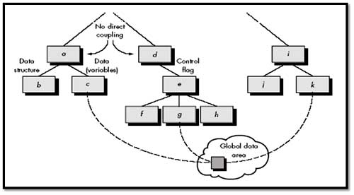
From the above figure, Modules a and d are subordinate to different modules. Each is unrelated and therefore no direct coupling occurs. Module c is subordinate to module aand is accessed via a conventional argument list, through which data are passed. As long as a simple argument list is present (i.e., simple data are passed; a one-to-one correspondence of items exists), low coupling (called data coupling) is exhibited in this portion of structure. A variation of data coupling, called stamp coupling is found when a portion of a data structure (rather than simple arguments) is passed via a module interface. This occurs between modules b and a.
Common coupling--Module c initializes the item. Later module g recomputed and updates the item. Let's assume that an error occurs and g updates the item incorrectly. Much later in processing module, k reads the item, attempts to process it, and fails, causing the software to abort. The apparent cause of abort is module k; the actual cause, module g. Diagnosing problems in structures with considerable common coupling is time consuming and difficult.
Evolution of Software Design
Early design work concentrated on criteria for the development of modular programs and methods for refining software structures in a top-down manner. Later work proposed methods for the translation of data flow or data structure into a design definition.
Today, the emphasis in software design has been on software architecture and the design patterns that can be used to implement software architectures.
Characteristics are common to all design methods
Design quality attributes
- Firmness – program should not have any bug that inhibits its functions.
- Commodity – suitable to its intended use.
- Delight - pleasurable to use
The design model provides detail about software data structures, architecture, interfaces, and components that are necessary to implement the system. The process by which the design model is developed is described by Belady [BEL81]:
“There are two major phases to any design process: diversification and convergence. Diversification is the acquisition of a repertoire of alternatives, the raw material of design: components, component solutions, and knowledge, all contained in catalogs, textbooks, and the mind. During convergence, the designer chooses and combines appropriate elements from this repertoire to meet the design objectives, as stated in the requirements document and as agreed to by the customer. The second phase is the gradual elimination of all but one particular configuration of components, and thus the creation of the final product.”
Well structured definition about what is design can be heard in words of Roger pressmen in his book Software Engineering as:
“Design is a meaningful engineering representation of something that is to be built. It can be traced to a customer’s requirements and at the same time assessed for quality against a set of predefined criteria for “good” design. In the software engineering context, design focuses on four major areas of concern: data, architecture, interfaces, and components. The concepts and principles discussed in this chapter apply to all four.”
1.1 Software Design
Software design model consists of 4 designs:
- Data/class Design
- Architectural Design
- Interface Design
- Component Design
Translating Analysis -> Design:
Translating Analysis to Design process involved following steps:
- Data/class design - Created by transforming the analysis model class-based elements into classes and data structures required to implement the software
- Architectural design - defines the relationships among the major structural elements of the software, it is derived from the class-based elements and flow-oriented elements of the analysis model
- Interface design - describes how the software elements, hardware elements, and end-users communicate with one another, it is derived from the analysis model scenario-based elements, flow-oriented elements, and behavioral elements
- Component-level design - created by transforming the structural elements defined by the software architecture into a procedural description of the software components using information obtained from the analysis model class-based elements, flow-oriented elements, and behavioral elements
- It ensures and provides us with representation of software that can be assessed for quality.
- It accurately translates customer’s requirements into a finished software product.
- It serves as foundation for all software engineering activities.
- Without design, it is difficult to assess Risk, Test and Quality
1.2 Software Design Process and Design Quality
Software(s/w) design is an iterative process through which requirements are translated into a “blueprint” for constructing the s/w. As design iteration occur, subsequent refinement leads to design representation at much lower levels of abstraction.
1.2.1 Goal of design process
- The design must implement all of the explicit requirements contained in the analysis model, and it must accommodate all of the implicit requirements desired by the customer.
- The design must be a readable, understandable guide for those who generate code and for those who test and subsequently support the software.
- The design should provide a complete picture of the software, addressing the data, functional, and behavioral domains from an implementation perspective.
Characteristics of good design
- A design should exhibit an architecture that: a. as been created using recognizable architectural styles or patterns, b. is composed of components that exhibit good design characteristics and c. can be implemented in an evolutionary fashion
- A design should be modular; that is, the software should be logically partitioned into elements or subsystems
- A design should contain distinct representations of data, architecture, interfaces, and components.
- A design should lead to data structures that are appropriate for the classes to be implemented and are drawn from recognizable data patterns.
- A design should lead to components that exhibit independent functional characteristics
- A design should lead to interfaces that reduce the complexity of connections between components and with the external environment.
- A design should be derived using a repeatable method that is driven by information obtained during software requirements analysis.
- A design should be represented using a notation that effectively communicates its meaning.
- S/W design is both a process and a model.
- Design process is sequence of steps that enable the designer to describe all aspects of the software to be built.
- Design model - created for software provides a variety of different views of the computer software
- The design process should not suffer from ‘tunnel vision.’ - Designer should consider alternative approaches.
- The design should be traceable to the analysis model - a single element of the design model often traces to multiple requirements, it is necessary to have a means for tracking how requirements have been satisfied by the design model.
- The design should not reinvent the wheel- use already exists design pattern because time is short and resources are limited.
- The design should “minimize the intellectual distance” between the software and the problem as it exists in the real world. – design should be self-explanatory
- The design should exhibit uniformity and integration – before design work begins rules of styles and format should be defined for a design team.
- The design should be structured to accommodate change
- The design should be structured to degrade gently, even when unusual data, events, or operating conditions are encountered.
- Design is not coding, coding is not design.
- The design should be assessed for quality as it is being created, not after the fact
- The design should be reviewed to minimize conceptual (semantic) errors.
Design concepts
Design concepts provide the necessary framework for “to get the thing on right way”.
- Abstraction
- Refinement
- Modularity
- Architecture
- Control Hierarchy
- Structural Partitioning
- Data Structure
- Software Procedure
- Information Hiding
At the highest level of abstraction – a solution is stated in broad terms. At lower level of abstraction – a more detailed description of the solution is provided. Two types of abstraction:
I. Procedural abstraction: Sequence of instructions that have a specific and limited function.
Ex. Open a door
Open implies long sequence of activities (e.g. walk to the door, grasp knob, turn knob and pull the door, etc).
II. Data abstraction: collection of data that describes a data object.
Ex. Open a door. – door is data object.
- Data abstraction for door would encompass a set of attributes that describe the door. (E.g. door type, swing direction, opening mechanism, etc.)
2. Refinement
Refinement is actually a process of elaboration. It begins with a statement of function (or description of information) that is defined at a high level of abstraction. That is, the statement describes function or information conceptually but provides no information about the internal workings of the function or the internal structure of the information.
Refinement causes the designer to elaborate on the original statement, providing more and more detail as each successive refinement (elaboration) occurs. Abstraction and refinement are complementary concepts. Abstraction enables a designer to specify procedure and data and yet suppress low-level details. Refinement helps the designer to expose low-level details as design progresses.
3. Modularity
Architecture and design pattern embody modularity. Software is divided into separately named and addressable components, sometimes called modules, which are integrated to satisfy problem requirement. Modularity is the single attribute of software that allows a program to be intellectually manageable. It leads to a “divide and conquer” strategy, in which a complex problem when you break into a manageable pieces.
Refer fig. that state that effort (cost) to develop an individual software module does decrease if the total number of modules increases. However as the no. of modules grows, the effort (cost) associated with integrating the modules also grows.
Modularity and software cost
Undermodularity and overmodularity should be avoided. But how do we know the vicinity of M? We modularize a design so that development can be more easily planned. Software increments can be defined and delivered. Changes can be more easily accommodated. Testing and debugging can be conducted more efficiently and long-term maintained can be conducted without serious side effects.
4. Architecture
Software architecture suggests “the overall structure of the software and the ways in which that structure provides conceptual integrity for a system. No. of different models can use to represent architecture.
- Structural Model- represent architecture as an organized collection of components
- Framework model– Increase level of design abstraction by identifying repeatable architectural design framework.
- Dynamic model– address behavior of the program architecture and indicating how system or structure configuration may change as a function.
- Process Model – focus on design of the business or technical process that the system must accommodate.
- Functional models – used to represent the functional hierarchy of a system.
5. Control Hierarchy
Control hierarchy, represents the organization of program components (modules) and implies a hierarchy of control. Different notations are used to represent control hierarchy for those architectural styles that are amenable to this representation. The most common is the treelike diagram that represents hierarchical control for call and return architectures.
In fig. depth and width provide an indication of the number of levels of control and overall span of control. Fan-out is a measure of the number of modules that are directly controlled by another module. Fan-in indicates how many modules directly control a given module. A module that controls another module is said to be superordinate to it, and conversely, a module controlled by another is said to be subordinate to the controller.
Ex. Module M is superordinate to modules a, b, and c.
Module h is subordinate to module e
6. Structural Partitioning
- Two types of Structure partitioning:
II. Vertical Partitioning
Horizontal Partitioning:
It defines separate branches of the modular hierarchy for each major program function. Control modules, represented in a darker shade are used to coordinate communication & execution between its functions. Horizontal partitioning defines three partitions—input, data transformation (often called processing) and output. Benefits of horizontal partitioning:
- software that is easier to test
- software that is easier to maintain
- propagation of fewer side effects
- software that is easier to extend
On the negative side (Drawback), horizontal partitioning often causes more data to be passed across module interfaces and can complicate the overall control of program flow.
Vertical Partitioning:
It is often referred as factoring. This suggests that control (decision making) and work should be distributed top-down in the program structure. Top-level modules should perform control functions and do little actual processing work. Modules that reside low in the structure should be the workers, performing all input, computation, and output tasks.
A change in a control module (high in the structure) will have a higher probability of propagating side effects to modules that are subordinate to it. A change to a worker module, given its low level in the structure, is less likely to cause the propagation of side effects. For this reason vertically partitioned structures are less likely to be susceptible to side effects when changes are made and will therefore be more maintainable.
7. Data Structure
Data structure is a representation of the logical relationship among individual elements of data.
A scalar item is the simplest of all data structures. It represents a single element of information that may be addressed by an identifier. When scalar items are organized as a list or contiguous group, a sequential vector is formed. When the sequential vector is extended to two, three, and ultimately, an arbitrary number of dimensions, an n-dimensional space is created. Most common n-dimensional space is the two-dimensional matrix
A linked list is a data structure that organizes contiguous scalar items, vectors, or spaces in a manner (called nodes) that enables them to be processed as a list.
A hierarchical data structure is implemented using multilinked lists that contain scalar items, vectors, and possibly, n-dimensional spaces.
Software Procedure
Software procedure focuses on the processing details of each module individually. Procedure must provide a precise specification of processing, including sequence of events, exact decision points, repetitive operations, and even data organization and structure.
8. Information Hiding
The principle of information hiding suggests that modules be "characterized by design decisions that (each) hides from all others modules.“ In other words, modules should be specified and designed so that information (algorithm and data) contained within a module is inaccessible to other modules that have no need for such information.
The intent of information hiding is to hide the details of data structure and procedural processing behind a module interface. It gives benefits when modifications are required during testing and maintenance because data and procedure are hiding from other parts of software, unintentional errors introduced during modification are less.
Effective Modular Design
- Effective modular design consist of three things:
- Functional Independence
- Cohesion
- Coupling
Functional Independence
Functional independence is achieved by developing modules with "single-minded“function and an "aversion" to excessive interaction with other modules. In other words - each module addresses a specific sub-function of requirements and has a simple interface when viewed from other parts of the program structure. Independence is important –
- Easier to develop
- Easier to Test and maintain
- Error propagation is reduced
- Reusable module.
- Cohesion is a measure of the relative functional strength of a module.
- Coupling is a measure of the relative interdependence among modules.
Cohesion is a natural extension of the information hiding concept. A cohesive module performs a single task within a software procedure, requiring little interaction with procedures being performed in other parts of a program. Simply state, a cohesive module should (ideally) do just one thing.
We always strive for high cohesion, although the mid-range of the spectrum is often acceptable. Low-end cohesiveness is much "worse" than middle range, which is nearly as "good" as high-end cohesion. So, designer should avoid low levels of cohesion when modules are designed. When processing elements of a module are related and must be executed in a specific order, procedural cohesion exists.
When all processing elements concentrate on one area of a data structure, communicational cohesion is present. High cohesion is characterized by a module that performs one distinct procedural task.
Types of cohesion
- A module that performs tasks that are related logically is logically cohesive.
- When a module contains tasks that are related by the fact that all must be executed with the same span of time, the module exhibits temporal cohesion.
- At the low-end of the spectrum, a module that performs a set of tasks that relate to each other loosely, called coincidentally cohesive.
As an example of low cohesion, consider a module that performs error processing for an engineering analysis package. The module is called when computed data exceed pre-specified bounds. It performs the following tasks:
(1) computes supplementary data based on original computed data,
(2) Produces an error report (with graphical content) on the user's workstation,
(3) Performs follow-up calculations requested by the user,
(4) Updates a database, and
(5) Enables menu selection for subsequent processing.
Although the preceding tasks are loosely related, each is an independent functional entity that might best be performed as a separate module. Combining the functions into a single module can serve only to increase the likelihood of error propagation when a modification is made to one of its processing tasks.
Coupling
The coupling depends on the interface complexity between modules, the point at which entry or reference is made to a module, and what data pass across the interface
In software design, we strive for lowest possible coupling. Simple connectivity among modules results in software that is easier to understand and less prone to a "ripple effect" caused when errors occur at one location and propagate through a system. It occurs because of design decisions made when structure was developed.
From the above figure, Modules a and d are subordinate to different modules. Each is unrelated and therefore no direct coupling occurs. Module c is subordinate to module aand is accessed via a conventional argument list, through which data are passed. As long as a simple argument list is present (i.e., simple data are passed; a one-to-one correspondence of items exists), low coupling (called data coupling) is exhibited in this portion of structure. A variation of data coupling, called stamp coupling is found when a portion of a data structure (rather than simple arguments) is passed via a module interface. This occurs between modules b and a.
- Coupling is characterized by passage of control between modules.
- “Control flag” (a variable that controls decisions in a subordinate or superordinate module) is passed between modules d and e (called control coupling).
- Relatively high levels of coupling occur when modules are communicated with external to software.
- External coupling is essential, but should be limited to a small number of modules with a structure.
- High coupling also occurs when a number of modules reference a global data area.
- Common coupling, no. of modules access a data item in a global data area
- So it does not mean “use of global data is bad”. It does mean that a software designer must be take care of this thing.
Common coupling--Module c initializes the item. Later module g recomputed and updates the item. Let's assume that an error occurs and g updates the item incorrectly. Much later in processing module, k reads the item, attempts to process it, and fails, causing the software to abort. The apparent cause of abort is module k; the actual cause, module g. Diagnosing problems in structures with considerable common coupling is time consuming and difficult.
Evolution of Software Design
Early design work concentrated on criteria for the development of modular programs and methods for refining software structures in a top-down manner. Later work proposed methods for the translation of data flow or data structure into a design definition.
Today, the emphasis in software design has been on software architecture and the design patterns that can be used to implement software architectures.
Characteristics are common to all design methods
- A mechanism for the translation of analysis model into a design representation,
- A notation for representing functional components and their interfaces.
- Heuristics for refinement and partitioning
- Guidelines for quality assessment.
Design quality attributes
- Acronym FURPS –
- Functionality
- Usability
- Reliability
- Performance
- Supportability
- Functionality – is assessed by evaluating the feature set and capabilities of the program.
- Functions that are delivered and security of the overall system.
- Usability – assessed by considering human factors, consistency & documentation.
- Reliability – evaluated by
- measuring the frequency and severity of failure.
- Accuracy of output results.
- Ability to recover from failure and predictability of the program.
- Performance - measured by processing speed, response time, resource consumption, efficiency.
- Supportability – combines the ability to extend the program (extensibility), adaptability and serviceability.
Published date : 27 May 2015 03:17PM