

Sakshi Education
The specific objectives of this lecture are to:
1.1. Rolling piston (fixed vane) type compressors:
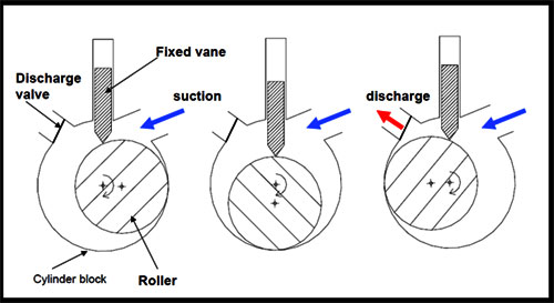
The Rolling piston or fixed vane type compressors are used in small refrigeration systems (up to 2 kW capacities) such as domestic refrigerators or air conditioners. These compressors belong to the class of positive displacement type as compression is achieved by reducing the volume of the refrigerant. In this type of compressors, the rotating shaft of the roller has its axis of rotation that matches with the centreline of the cylinder; however, it is eccentric with respect to the roller (Figure 1.1). This eccentricity of the shaft with respect to the roller creates suction and compression of the refrigerant as shown in Fig.1.1. A single vane or blade is positioned in the non-rotating cylindrical block. The rotating motion of the roller causes a reciprocating motion of the single vane.
Fig.1.1: Working principle of a rolling piston type compressor
As shown in Fig.1.1, this type of compressor does not require a suction valve but requires a discharge valve. The sealing between the high and low pressure sides has to be provided:
The leakage is controlled through hydrodynamic sealing and matching between the mating components. The effectiveness of the sealing depends on the clearance, compressor rate, surface finish and oil viscosity. Close tolerance and great surface finishing is obliged to minimize interior leakage. Dissimilar to in responding compressors, the little freedom volume loaded with high-pressure refrigerant does not expand, but rather just blends with the suction refrigerant in the suction space. Therefore, the volumetric efficiency does not reduce radically with expanding pressure proportion, showing little re-development misfortunes. The compressor runs easily and is moderately tranquil as the refrigerant flow is continuous.
The mass flow rate of refrigerant through the compressor is given by:
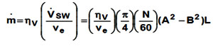
Where,
A = Inner diameter of the cylinder
B = Diameter of the roller
L = Length of the cylinder block
N = Rotation speed, RPM
?v = Volumetric efficiency
Ve = specific volume of refrigerant at suction
1.2. Multiple vane type compressors:
As shown Fig.1.2, in multiple vane type compressors, the axis of turn concurs with the centre of the roller (O), however, it is eccentric with respect to the centre of the cylinder (O'). The rotor consists of various spaces with sliding vanes. Amid the running of the compressor, the sliding vanes, which are regularly made of non-metallic materials, are held against the chamber because of centrifugal forces. The quantity of pressure strokes created in one upheaval of the rotor is equivalent to the quantity of sliding vanes, in this way a 4-vane compressor delivers 4 pressure strokes in one rotation. In these compressors, sealing is needed between the vanes and chamber, between the vanes and the spaces on the rotor and between the rotor and the end plate. However, since pressure difference over every space is just a small amount of the aggregate pressure difference, the sealing is not as basic as in fixed vane type compressor.
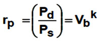
This type of compressor does not oblige suction or discharge valves. However, as demonstrated in Fig.1.3, check valves are utilized on discharge side to anticipate reverse rotation during off-time because of pressure difference. Since there are no discharge valves, the compacted refrigerant is opened to the discharge port when it has been packed through a fixed volume ratio, contingent on the geometry. This infers that these compressors have a fixed implicit volume ratio. The implicit volume ratio is characterized as "the ratio of a cell as it is cut off from the suction port to its volume before it opens to the discharge port". Since the volume ratio is fixed, the pressure ratio, rp is given by:
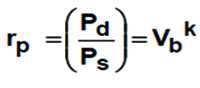
Where, Pd and Ps are the discharge and suction pressures, Vb is the built-in volume ratio and k is the index of compression.
Since no centrifugal power is available when the compressor is off, the different vanes won't be squeezed against the cylinder walls during the off-period. Accordingly, high pressure refrigerant from the discharge side can flow once more into the side and pressure equalization between high and low pressure sides occur. This is gainful from the compressor motor perspective as it diminishes the obliged beginning Torque. However, this acquaints cycling misfortune due with the passage of high pressure and hot refrigerant liquid into the evaporator. Henceforth, normally a non-return check valve is utilized on the discharge side which keeps the section of refrigerant liquid from high pressure side into evaporator through the compressor during off- time; in the meantime there will be pressure equalization over the vanes of the compressor.
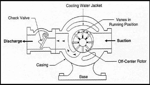
Fig.1.3: Sectional view of a multiple vane, rotary compressor
1.3. Characteristics of rotary, vane type compressors:
Rotary vane type compressors have low mass-to-displacement ratio, which in combination with compact size makes them ideal for transport applications. The compressors are normally oil-flooded type; hence, oil separators are required. Both single-stages (up to –40oC evaporator temperature and 60oC condensing temperature) and two-stage (up to –50oC evaporator temperature) compressors with the cooling capacity in the range of 2 to 40 kW are available commercially. The cooling capacity is normally controlled either by compressor speed regulation or suction gas throttling. Currently, these compressors are available for a wide range of refrigerants such as R 22, ammonia, R 404a etc.
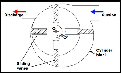
Fig.1.2: Working principle of a multiple vane, rotary compressor
1.4. Rotary, screw compressors:
The rotary screw compressors can be either twin-screw type or single-screw type.
1.4.1. Twin-screw compressor:
The twin-screw type compressor consists of two mating helically grooved rotors, one male and the other female. Generally the male rotor drives the female rotor. The male rotor has lobes, while the female rotor has flutes or gullies. The frequently used lobe-gully combinations are [4,6], [5,6] and [5,7]. Figure 1.4 shows the [4,6] combination. For this [4,6] combination, when the male rotor rotates at 3600 RPM, the female rotor rotates at 2400 RPM.
As shown in Fig.1.5, the flow is mainly in the axial direction. Suction and compression take place as the rotors unmesh and mesh. When one lobe-gully combination begins to unmesh the opposite lobe-gully combination begins to mesh.
With 4 male lobes rotating at 3600 RPM, 4 inter lobe volumes are per revolution, thus giving 4 X 3600 = 14400 discharges per minute.
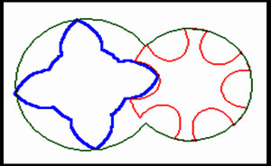
Fig.1.4: Twin-screw compressor with 4 male lobes and 6 female gullies
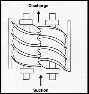
Fig.1.5: Direction of refrigerant flow in a twin-screw compressor
Discharge takes place at a point decided by the designed built-in volume ratio, which depends entirely on the location of the delivery port and geometry of the compressor. Since the built-in volume ratio is fixed by the geometry, a particular compressor is designed for a particular built-in pressure ratio. However, different built-in ratios can be obtained by changing the position of the discharge port. The built-in pressure ratio, rp given by:
Where, Pd and Ps are the discharge and suction pressures, Vb is the built-in volume ratio and k is the index of compression.
If the built-in pressure at the end of compression is not exactly the consolidating pressure, high pressure refrigerant from discharge complex flows once again into the inter lobe space when the discharge port is uncovered. This is called as under compression. On the other hand, if the implicit pressure at the end of compression is higher than the gathering pressure, then the compacted refrigerant surges out in an intemperate development when the port is uncovered (over-compression). Both under-compression and over-compression are undesirable as they prompt misfortune in efficiency.
Lubrication and sealing between the rotors is acquired by infusing lubricating oil between the rotors. The oil additionally helps in cooling the compressor; thus high pressure ratios (up to 20:1) are conceivable without overheating the compressor. The capacity of the screw compressor is normally controlled with the assistance of a slide valve. As the slide valve is opened measure of suction refrigerant breaks to the suction side without being packed. This yields a smooth capacity control from 100 percent down to 10 percent of full load. It is watched that the force data is approximately proportional to refrigeration capacity up to around 30 percent; however, the efficiency diminishes quickly, thereafter.
Figure 1.6 demonstrates the compression efficiency of a twin-screw compressor as a component of pressure ratio and implicit volume ratio. It can be seen that for a given implicit volume ratio, the efficiency achieves a top at a specific optimum pressure ratio. The estimation of these optimum pressure ratio increments with inherent volume ratio as indicated in the figure. On the off chance that the outline condition compares to the optimum pressure ratio, then the compression efficiency drops as the framework operates at off-configuration conditions. However, when operated at the optimum pressure ratio, the efficiency is much higher than other types of compressors.
As the rotor normally rotates at high speeds, screw compressors can handle genuinely a lot of refrigerant flow rates contrasted with other positive displacement type compressors. Screw compressors are accessible in the capacity range of 70 to 4600 kW. They by and large rival high capacity reciprocating compressors and low capacity centrifugal compressors. They are accessible for a wide mixed bag of refrigerants and applications. Contrasted with reciprocating compressors, screw compressors are adjusted and subsequently don't experience the ill effects of vibration problems.
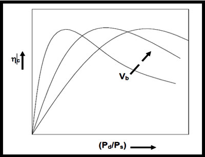
Fig.1.6: Variation of compression efficiency of a twin-screw compressor with pressure ratio and built-in volume ratio
Twin-screw compressors are rugged and are shown to be more reliable than reciprocating compressors; they are shown to run for 30000 – 40000 hours between major overhauls. They are compact compared to reciprocating compressors in the high capacity range.
1.4.2. Single-screw compressors:
As the name suggests, single screw compressors consist of a solitary helical screw and two planet wheels or gate rotors. The helical screw is housed in a round and hollow casing with suction port toward one side and discharge port at the flip side as indicated in Fig. 1.7. Suction and compression are acquired as the screw and gate rotors un mesh and mesh. The high and low pressure districts in the cylinder casing are separated by the gate rotors. The single screw is normally determined by an electric motor. The gate rotors are normally made of plastic materials.
Little power is obliged to rotate the gate rotors as the frictional misfortunes between the metallic screw and the plastic gate rotors are little. It is likewise conceivable to plan the compressors with a solitary gate rotor. Like twin-screw, lubrication, sealing and compressor cooling is accomplished by injecting lubricating oil into the compressor. An oil separator, oil cooler and pump are obliged to circulate the lubricating oil. It is likewise conceivable to accomplish this by injecting liquid refrigerant, in which case there is no requirement for an oil separator.
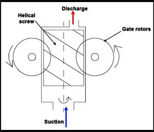
Fig.1.7: Working principle of a single-screw compressor
Scroll compressors:
Scroll compressors are orbital movement, positive displacement type compressors, in which suction and compression is acquired by utilizing two mating, spiral shaped, scroll members, one fixed and the other orbiting. Figure 1.8 demonstrates the working rule of scroll compressors. Figures 1.9 and 1.10 demonstrate the constructional points of interest of scroll compressors. As indicated in Fig.1.8, the compression procedure includes three orbits of the orbiting scroll. In the first orbit, the scrolls ingest and trap two pockets of suction gas.
During the second orbit, the two pockets of gas are compacted to an intermediate pressure. In the final orbit, the two pockets achieve discharge pressure and are all the while opened to the discharge port. This concurrent procedure of suction, intermediate compression and discharge prompts the smooth continuous compression procedure of the scroll compressor. One section that is not demonstrated in this diagram but rather is crucial to the operation of the scroll is the opposition to rotation coupling. This gadget keeps up a fixed rakish relation of 180 degrees between the fixed and orbiting scrolls.
This fixed rakish relation, combined with the development of the orbiting scroll, is the basis for the formation of gas compression pockets. As indicated in Figs.1.9 and 1.10, every scroll member is open toward one side and bound by a base plate at the flip side. They are fitted to form pockets of refrigerant between their particular base plates and different lines of contacts between the scroll walls. Compressor capacity is normally controlled by variable rate inverter drives.
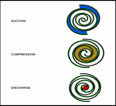
Fig.1.8: Working principle of a scroll compressor
Currently, the scroll compressors are used in small capacity (3 to 50 kW) refrigeration, air conditioning and heat pump applications. They are normally of hermetic type. Scroll compressors offer several advantages such as:
- Working principle and characteristics of a fixed vane, rolling piston type compressor.
- Working principle and characteristics of a multiple vane, rotary compressor.
- Working principle and characteristics of a twin-screw type compressor.
- Working principle and characteristics of a single-screw type compressor.
- Working principle, characteristics and specific advantages of a scroll compressor
1.1. Rolling piston (fixed vane) type compressors:
The Rolling piston or fixed vane type compressors are used in small refrigeration systems (up to 2 kW capacities) such as domestic refrigerators or air conditioners. These compressors belong to the class of positive displacement type as compression is achieved by reducing the volume of the refrigerant. In this type of compressors, the rotating shaft of the roller has its axis of rotation that matches with the centreline of the cylinder; however, it is eccentric with respect to the roller (Figure 1.1). This eccentricity of the shaft with respect to the roller creates suction and compression of the refrigerant as shown in Fig.1.1. A single vane or blade is positioned in the non-rotating cylindrical block. The rotating motion of the roller causes a reciprocating motion of the single vane.
Fig.1.1: Working principle of a rolling piston type compressor
As shown in Fig.1.1, this type of compressor does not require a suction valve but requires a discharge valve. The sealing between the high and low pressure sides has to be provided:
- Along the line of contact between roller and cylinder block
- Along the line of contact between vane and roller, and
- Between the roller and end-pates
The leakage is controlled through hydrodynamic sealing and matching between the mating components. The effectiveness of the sealing depends on the clearance, compressor rate, surface finish and oil viscosity. Close tolerance and great surface finishing is obliged to minimize interior leakage. Dissimilar to in responding compressors, the little freedom volume loaded with high-pressure refrigerant does not expand, but rather just blends with the suction refrigerant in the suction space. Therefore, the volumetric efficiency does not reduce radically with expanding pressure proportion, showing little re-development misfortunes. The compressor runs easily and is moderately tranquil as the refrigerant flow is continuous.
The mass flow rate of refrigerant through the compressor is given by:
Where,
A = Inner diameter of the cylinder
B = Diameter of the roller
L = Length of the cylinder block
N = Rotation speed, RPM
?v = Volumetric efficiency
Ve = specific volume of refrigerant at suction
1.2. Multiple vane type compressors:
As shown Fig.1.2, in multiple vane type compressors, the axis of turn concurs with the centre of the roller (O), however, it is eccentric with respect to the centre of the cylinder (O'). The rotor consists of various spaces with sliding vanes. Amid the running of the compressor, the sliding vanes, which are regularly made of non-metallic materials, are held against the chamber because of centrifugal forces. The quantity of pressure strokes created in one upheaval of the rotor is equivalent to the quantity of sliding vanes, in this way a 4-vane compressor delivers 4 pressure strokes in one rotation. In these compressors, sealing is needed between the vanes and chamber, between the vanes and the spaces on the rotor and between the rotor and the end plate. However, since pressure difference over every space is just a small amount of the aggregate pressure difference, the sealing is not as basic as in fixed vane type compressor.
This type of compressor does not oblige suction or discharge valves. However, as demonstrated in Fig.1.3, check valves are utilized on discharge side to anticipate reverse rotation during off-time because of pressure difference. Since there are no discharge valves, the compacted refrigerant is opened to the discharge port when it has been packed through a fixed volume ratio, contingent on the geometry. This infers that these compressors have a fixed implicit volume ratio. The implicit volume ratio is characterized as "the ratio of a cell as it is cut off from the suction port to its volume before it opens to the discharge port". Since the volume ratio is fixed, the pressure ratio, rp is given by:
Where, Pd and Ps are the discharge and suction pressures, Vb is the built-in volume ratio and k is the index of compression.
Since no centrifugal power is available when the compressor is off, the different vanes won't be squeezed against the cylinder walls during the off-period. Accordingly, high pressure refrigerant from the discharge side can flow once more into the side and pressure equalization between high and low pressure sides occur. This is gainful from the compressor motor perspective as it diminishes the obliged beginning Torque. However, this acquaints cycling misfortune due with the passage of high pressure and hot refrigerant liquid into the evaporator. Henceforth, normally a non-return check valve is utilized on the discharge side which keeps the section of refrigerant liquid from high pressure side into evaporator through the compressor during off- time; in the meantime there will be pressure equalization over the vanes of the compressor.
Fig.1.3: Sectional view of a multiple vane, rotary compressor
1.3. Characteristics of rotary, vane type compressors:
Rotary vane type compressors have low mass-to-displacement ratio, which in combination with compact size makes them ideal for transport applications. The compressors are normally oil-flooded type; hence, oil separators are required. Both single-stages (up to –40oC evaporator temperature and 60oC condensing temperature) and two-stage (up to –50oC evaporator temperature) compressors with the cooling capacity in the range of 2 to 40 kW are available commercially. The cooling capacity is normally controlled either by compressor speed regulation or suction gas throttling. Currently, these compressors are available for a wide range of refrigerants such as R 22, ammonia, R 404a etc.
Fig.1.2: Working principle of a multiple vane, rotary compressor
1.4. Rotary, screw compressors:
The rotary screw compressors can be either twin-screw type or single-screw type.
1.4.1. Twin-screw compressor:
The twin-screw type compressor consists of two mating helically grooved rotors, one male and the other female. Generally the male rotor drives the female rotor. The male rotor has lobes, while the female rotor has flutes or gullies. The frequently used lobe-gully combinations are [4,6], [5,6] and [5,7]. Figure 1.4 shows the [4,6] combination. For this [4,6] combination, when the male rotor rotates at 3600 RPM, the female rotor rotates at 2400 RPM.
As shown in Fig.1.5, the flow is mainly in the axial direction. Suction and compression take place as the rotors unmesh and mesh. When one lobe-gully combination begins to unmesh the opposite lobe-gully combination begins to mesh.
With 4 male lobes rotating at 3600 RPM, 4 inter lobe volumes are per revolution, thus giving 4 X 3600 = 14400 discharges per minute.
Fig.1.4: Twin-screw compressor with 4 male lobes and 6 female gullies
Fig.1.5: Direction of refrigerant flow in a twin-screw compressor
Discharge takes place at a point decided by the designed built-in volume ratio, which depends entirely on the location of the delivery port and geometry of the compressor. Since the built-in volume ratio is fixed by the geometry, a particular compressor is designed for a particular built-in pressure ratio. However, different built-in ratios can be obtained by changing the position of the discharge port. The built-in pressure ratio, rp given by:
Where, Pd and Ps are the discharge and suction pressures, Vb is the built-in volume ratio and k is the index of compression.
If the built-in pressure at the end of compression is not exactly the consolidating pressure, high pressure refrigerant from discharge complex flows once again into the inter lobe space when the discharge port is uncovered. This is called as under compression. On the other hand, if the implicit pressure at the end of compression is higher than the gathering pressure, then the compacted refrigerant surges out in an intemperate development when the port is uncovered (over-compression). Both under-compression and over-compression are undesirable as they prompt misfortune in efficiency.
Lubrication and sealing between the rotors is acquired by infusing lubricating oil between the rotors. The oil additionally helps in cooling the compressor; thus high pressure ratios (up to 20:1) are conceivable without overheating the compressor. The capacity of the screw compressor is normally controlled with the assistance of a slide valve. As the slide valve is opened measure of suction refrigerant breaks to the suction side without being packed. This yields a smooth capacity control from 100 percent down to 10 percent of full load. It is watched that the force data is approximately proportional to refrigeration capacity up to around 30 percent; however, the efficiency diminishes quickly, thereafter.
Figure 1.6 demonstrates the compression efficiency of a twin-screw compressor as a component of pressure ratio and implicit volume ratio. It can be seen that for a given implicit volume ratio, the efficiency achieves a top at a specific optimum pressure ratio. The estimation of these optimum pressure ratio increments with inherent volume ratio as indicated in the figure. On the off chance that the outline condition compares to the optimum pressure ratio, then the compression efficiency drops as the framework operates at off-configuration conditions. However, when operated at the optimum pressure ratio, the efficiency is much higher than other types of compressors.
As the rotor normally rotates at high speeds, screw compressors can handle genuinely a lot of refrigerant flow rates contrasted with other positive displacement type compressors. Screw compressors are accessible in the capacity range of 70 to 4600 kW. They by and large rival high capacity reciprocating compressors and low capacity centrifugal compressors. They are accessible for a wide mixed bag of refrigerants and applications. Contrasted with reciprocating compressors, screw compressors are adjusted and subsequently don't experience the ill effects of vibration problems.
Fig.1.6: Variation of compression efficiency of a twin-screw compressor with pressure ratio and built-in volume ratio
Twin-screw compressors are rugged and are shown to be more reliable than reciprocating compressors; they are shown to run for 30000 – 40000 hours between major overhauls. They are compact compared to reciprocating compressors in the high capacity range.
1.4.2. Single-screw compressors:
As the name suggests, single screw compressors consist of a solitary helical screw and two planet wheels or gate rotors. The helical screw is housed in a round and hollow casing with suction port toward one side and discharge port at the flip side as indicated in Fig. 1.7. Suction and compression are acquired as the screw and gate rotors un mesh and mesh. The high and low pressure districts in the cylinder casing are separated by the gate rotors. The single screw is normally determined by an electric motor. The gate rotors are normally made of plastic materials.
Little power is obliged to rotate the gate rotors as the frictional misfortunes between the metallic screw and the plastic gate rotors are little. It is likewise conceivable to plan the compressors with a solitary gate rotor. Like twin-screw, lubrication, sealing and compressor cooling is accomplished by injecting lubricating oil into the compressor. An oil separator, oil cooler and pump are obliged to circulate the lubricating oil. It is likewise conceivable to accomplish this by injecting liquid refrigerant, in which case there is no requirement for an oil separator.
Fig.1.7: Working principle of a single-screw compressor
Scroll compressors:
Scroll compressors are orbital movement, positive displacement type compressors, in which suction and compression is acquired by utilizing two mating, spiral shaped, scroll members, one fixed and the other orbiting. Figure 1.8 demonstrates the working rule of scroll compressors. Figures 1.9 and 1.10 demonstrate the constructional points of interest of scroll compressors. As indicated in Fig.1.8, the compression procedure includes three orbits of the orbiting scroll. In the first orbit, the scrolls ingest and trap two pockets of suction gas.
During the second orbit, the two pockets of gas are compacted to an intermediate pressure. In the final orbit, the two pockets achieve discharge pressure and are all the while opened to the discharge port. This concurrent procedure of suction, intermediate compression and discharge prompts the smooth continuous compression procedure of the scroll compressor. One section that is not demonstrated in this diagram but rather is crucial to the operation of the scroll is the opposition to rotation coupling. This gadget keeps up a fixed rakish relation of 180 degrees between the fixed and orbiting scrolls.
This fixed rakish relation, combined with the development of the orbiting scroll, is the basis for the formation of gas compression pockets. As indicated in Figs.1.9 and 1.10, every scroll member is open toward one side and bound by a base plate at the flip side. They are fitted to form pockets of refrigerant between their particular base plates and different lines of contacts between the scroll walls. Compressor capacity is normally controlled by variable rate inverter drives.
Fig.1.8: Working principle of a scroll compressor
Currently, the scroll compressors are used in small capacity (3 to 50 kW) refrigeration, air conditioning and heat pump applications. They are normally of hermetic type. Scroll compressors offer several advantages such as:
- Large suction and discharge ports reduce pressure losses during suction and discharge
- Physical separation of suction and compression reduce heat transfer to suction gas, leading to high volumetric efficiency
- Volumetric efficiency is also high due to very low re-expansion losses and continuous flow over a wide range of operating conditions
- Flatter capacity versus outdoor temperature curves
- High compression efficiency, low noise and vibration compared to reciprocating compressors
- Compact with minimum number of moving parts
Published date : 16 Jun 2015 05:59PM