

Sakshi Education
Nagendra M<br/>
CBM Engineer, Hindusthan Zink .Ltd
Objectives of the lesson:
1.1. Introduction
Refrigeration may be characterized as the procedure of accomplishing and keeping up a temperature underneath that of the surroundings, the point of being to cool some item or space to the obliged temperature. A standout amongst the most imperative applications of refrigeration has been the protection of perishable nourishment items by putting away them at low temperatures. Refrigeration frameworks are likewise utilized broadly for giving warm solace to individuals by method for cooling. Cooling alludes to the treatment of air to all the while control its temperature, dampness content, cleanliness, smell and course, as needed by inhabitants, a methodology, or items in the space. The historical backdrop of refrigeration is exceptionally intriguing following each part of it, the accessibility of refrigerants, the prime movers and the advancements in compressors and the systems for refrigeration all are a piece of it. The French researcher Roger Thývenot has composed a fabulous book on the historical backdrop of refrigeration all through the world.
1.2. Natural Refrigeration
In long time past days refrigeration was accomplished by common means, for example, the utilization of ice or evaporative cooling. In prior times, ice was either:
In 1806, Frederic Tudor started the exchange ice by cutting it from the Hudson River and lakes of Massachusetts and sending out it to different nations including India. In India Tudor's ice was less expensive than the provincially made ice by nocturnal cooling. The ice exchange North America was a prospering business. Ice was transported to southern conditions of America in train compartments protected by 0.3 m of stopper protection. Exchanging ice was likewise famous in a few different nations, for example, Great Britain, Russia, Canada, Norway and France. In these nations ice was either transported from colder areas or was reaped in winter and put away in ice houses for utilization in summer. The ice exchange arrived at its crest in 1872 when America alone sent out 225000 tons of ice to different nations the extent that China and Australia. Notwithstanding, with the appearance of counterfeit refrigeration the ice exchange slowly declined.
1.2.1. Specialty of Ice making by Nocturnal Cooling:
The craft of making ice by nocturnal cooling was consummated in India. In this system ice was made by keeping a meagre layer of water in a shallow earthen tray, and after that presenting the tray to the night sky. Compacted feed of around 0.3 m thickness was utilized as protection. The water looses warm by radiation to the stratosphere, which is at around -55°C and by ahead of schedule morning hours the water in the trays stops to ice. This technique for ice creation was exceptionally prominent in India.
1.2.2. Evaporative Cooling:
As the name shows, evaporative cooling is the procedure of lessening the temperature of a framework by vanishing of water. Individuals sweat and disseminate their metabolic hotness by evaporative cooling if the surrounding temperature is more than skin temperature. Creatures, for example, the hippopotamus and wild ox cover themselves with mud for evaporative cooling. Evaporative cooling has been utilized as a part of India for a considerable length of time to get cool water in summer by putting away the water in earthen pots. The water saturates through the pores of earthen vessel to its external surface where it vanishes to the encompassing, engrossing its inert hotness to some extent from the vessel, which cools the water. Suitably spotted stacks in the rooms expanded the upward stream of warm air, which was supplanted by cool air. Evaporative cooling by putting wet straw tangles on the windows is additionally exceptionally regular in India. The straw mat produced using "khus" adds its inborn fragrance likewise to the air. Presently a-days desert coolers are being utilized as a part of hot and dry territories to give cooling in summer.
1.2.3. Cooling by Salt Solutions:
Certain substances, for example, regular salt, when added to water break down in water and retain its hotness of arrangement from water (endothermic procedure). This lessens the temperature of the arrangement (water+salt). Sodium Chloride salt (NaCl) can yield temperatures up to -20°C and Calcium Chloride (CaCl2) up to - 50°C in legitimately protected holders. In any case, as it is this procedure has constrained application, as the broke up salt must be recouped from its answer by warm in.
1.3. Artificial Refrigeration
Refrigeration as it is known nowadays is delivered by manufactured means. Despite the fact that it is exceptionally hard to make a reasonable outline in the middle of regular and manufactured refrigeration, it is by and large concurred that the historical backdrop of fake refrigeration started in the year 1755, when the Scottish educator William Cullen made the first refrigerating machine, which could deliver a little amount of ice in the lab. Taking into account the working standard, refrigeration frameworks can be named vapour squeezing frameworks, vapour ingestion frameworks, gas cycle frameworks and so on.
1.3.1. Vapour Compression Refrigeration Systems:
The premise of advanced refrigeration is the capacity of fluids to retain huge amounts of hotness as they bubble and dissipate. Educator William Cullen of the University of Edinburgh exhibited this in 1755 by putting some water in warm contact with ether under a beneficiary of a vacuum pump. The dissipation rate of ether expanded because of the vacuum pump and water could be solidified. This methodology includes two thermodynamic ideas, the vapour weight and the idle hotness. A fluid is in warm harmony with its own particular vapour at a weight called the immersion weight, which relies on upon the temperature alone.
In the event, that the weight is expanded for instance in a weight cooker, the water bubbles at higher temperature. The second idea is that the vanishing of fluid obliges inactive high temperature amid dissipation. On the off chance that idle high temperature is removed from the fluid, the fluid gets cooled. The temperature of ether will stay consistent the length of the vacuum pump keeps up a weight equivalent to immersion weight at the fancied temperature. This requires the evacuation of every last one of vapours shaped because of vaporization. In the event that a lower temperature is coveted, then a lower immersion weight will must be kept up by the vacuum pump. The segment of the cutting edge refrigeration framework where cooling is created by this technique is called evaporator.
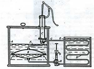
Mechanical assembly depicted by Jacob Perkins in his patent detail of 1834. The refrigerant bubbles in evaporator B taking high temperature from encompassing water in holder A. The pump C draws vapour away and packs it to higher weight at which it can consolidate to fluids in tubes D, giving out high temperature to water in vessel E. Consolidated fluid moves through the weight stacked valve H, which keeps up the distinction of weight between the condenser and evaporator. The little pump above H is utilized for accusing the contraption of refrigerant.
John Hague made Perkins' outline into working model with a few changes. This Perkins machine is demonstrated in Fig.1.2. The most punctual vapour squeezing framework utilized either sulphuric (ethyl) or methyl ether. The American engineer Alexander Twining (1801-1884) got a British patent in 1850 for a vapour packing framework by utilization of ether, NH3 and CO2.
The man in charge of making a viable vapour layering refrigeration framework was James Harrison who took a patent in 1856 for a vapour packing framework utilizing ether, liquor or smelling salts. Charles Tellier of France licensed in 1864, refrigeration framework utilizing dimethyl ether which has a typical breaking point of -23.6
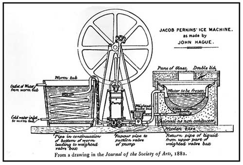
Fig.1.2. Perkins machine built by John Hague
Carl von Linde in Munich presented twofold acting alkali compressor. It obliged weights of more than 10 airs in the condenser. Since the typical breaking point of smelling salts is -33.3°C, vacuum was not needed on the low weight side. From that point forward alkali is utilized broadly as a part of expansive refrigeration plants.
1.3.1.1. Domestic refrigeration systems:
The household icebox utilizing regular ice (residential cooler) was designed in 1803 and was utilized for just about 150 years without much adjustment. The local cooler used to be made of wood with suitable protection. Ice used to be kept at the highest point of the crate, and low temperatures are created in the container because of high temperature exchange from ice by regular convection. A trickle skillet is utilized to gather the water shaped because of the softening of ice. The case must be recharged with new ice once all the ice dissolves.
In spite of the fact that the idea is very straightforward, the household refrigerator experienced a few impediments. The client needs to recharge the ice when it is devoured, and the most minimal temperatures that could be created inside the compartment are constrained.
General Electric Company presented the first residential icebox in 1911, took after via Frigidaire in 1915. Kelvinator dispatched the household mechanical cooler in 1918 in USA. In 1925, USA had around 25 million local iceboxes of which just 75000 were mechanical. Be that as it may, the assembling of household iceboxes became quickly, and by 1949 around 7 million residential coolers were delivered every year. With the generation volumes expanding the value fell pointedly (the cost was 600 dollars in 1920 and 155 dollars in 1940). The beginning household coolers utilized principally sulphur dioxide as refrigerant. A few units utilized methyl chloride and methylene chloride. These refrigerants were supplanted by Freon-12 in 1930s. In the first place these fridges were outfitted with open sort compressors determined by sash drive. General Electric Company presented the first icebox with a hermetic compressor in 1926. Before long the open sort compressors were totally supplanted by the hermetic compressors.
1.3.1.2. Air conditioning systems:
Refrigeration frameworks are likewise utilized for giving cooling and dehumidification in summer for individual solace (ventilating). The primary aerating and cooling frameworks were utilized for mechanical and in addition solace ventilating. Eastman Kodak introduced the first aerating and cooling framework in 1891 in Rochester, New York for the capacity of photographic movies. An aerating and cooling framework was introduced in a printing press in 1902 and in a phone trade in Hamburg in 1904. Numerous frameworks were introduced in tobacco and material production lines around 1900. The main local cooling framework was introduced in a house in Frankfurt in 1894. A private library in St Louis, USA was ventilated in 1895, and a clubhouse was aerated and cooled in Monte Carlo in 1901. Endeavours have likewise been made to aerate and cool traveller rail mentors utilizing ice.
Figure 1.3 demonstrates the essential parts of a vapour layering refrigeration framework. As indicated in the figure the essential framework comprises of an evaporator, compressor, condenser and an extension valve. The refrigeration impact is acquired exposed district as hotness is removed by the vaporization of refrigerant in the evaporator. The refrigerant vapour from the evaporator is layered in the compressor to a high weight at which its immersion temperature is more noteworthy than the encompassing or some other hotness sink. Consequently when the high weight, high temperature refrigerant moves through the condenser, build up of the vapour into fluid happens by hotness dismissal to the high temperature sink. To finish the cycle, the high weight fluid is made to course through a development valve. In the development valve the weight and temperature of the refrigerant diminishing. This low weight and low temperature refrigerant vapor vanishes in the evaporator taking hotness from the frosty locale. It ought to be watched that the framework works on a shut cycle. The framework obliges enter as mechanical work. It concentrates heat from a chilly space and rejects hotness to a high temperature high temperature sink.
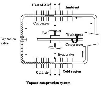
Fig.1.3. Schematic of a basic vapour compression refrigeration system
A refrigeration framework can likewise be utilized as a hotness pump, in which the helpful yield is the high temperature hotness rejected at the condenser. Then again, a refrigeration framework can be utilized for giving cooling as a part of summer and warming in winter. Such frameworks have been manufactured and are accessible now.
1.3.2. Vapour Absorption Refrigeration Systems:
John Leslie in 1810 kept H2SO4 and water in two different containers joined together. H2SO4 has high fondness for water. It assimilates water vapour and this turns into the rule of evacuating the vanished water vapour obliging no compressor or pump. H2SO4 is a permeable in this framework that must be reused by warming to dispose of the consumed water vapour, for consistent operation. Windhausen in 1878 utilized this rule for retention refrigeration framework, which took a shot at H2SO4. Ferdinand Carre designed water alkali ingestion framework in 1860. Water is a solid retentive of NH3. In the event that NH3 is kept in a vessel that is presented to an alternate vessel containing water, the solid assimilation capability of water will result in dissipation of NH3 obliging no compressor to drive the vapours.
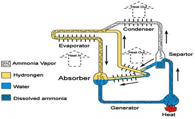
Fig.1.5 Schematic diagram of a fluid vapour absorption refrigeration system
An alternate variety of vapour assimilation framework is the one taking into account Lithium bromide-water. This framework is utilized for chilled water cooling framework. This is a descendent of Windhausen's machine with LiBr supplanting H2SO4. In this framework LiBr is the permeable and water is the refrigerant. This framework meets expectations at vacuum weights. The condenser and the generator are housed in one round and hollow vessel and the evaporator and the safeguard are housed in second vessel. This additionally runs on second rate vitality obliging a kettle or procedure steam.
1.3.3. Solar Energy based Refrigeration System:
Endeavours have been made to run vapour ingestion framework by sun oriented vitality with concentrating and level plate sun based gatherers. A few little sun oriented assimilation refrigeration frameworks have been made around 1950s in a few nations. Teacher G.O.G. L??f of America is one of the pioneers in the range of sunlight based refrigeration utilizing level plate gatherers. A sun based refrigeration framework that could deliver 250 kg of ice every day was introduced in Tashkent, USSR in 1953. This framework utilized an allegorical mirror of 10 m2 territory for concentrating the sunlight based radiation. F. Trombe introduced an ingestion machine with a cylinder-allegorical mirror of 20 m2 at Monologues, France, which delivered 100 kg of ice every day.
Genuine thought to sun oriented refrigeration framework was given since 1965, because of the lack of fossil fuel based vitality sources. LiBr-water based frameworks have been produced for cooling purposes. The primary sunlight based ventilating framework was introduced in a trial sun oriented house in University of Queensland, Australia in 1966. After this few frameworks in view of sunlight based vitality were inherent numerous parts of the world including India. In 1976, there were around 500 sun oriented retention frameworks in USA alone. Pretty much all these were in view of LiBr-water as these frameworks don't require high warming temperatures. These frameworks were for the most part utilized for space ventilating. Irregular ingestion framework in light of sun powered vitality have additionally been constructed and worked effectively. In these frameworks, the cooling impact is gotten amid the evening, while the framework gets "charged" amid the day utilizing sun based vitality. Despite the fact that the effectiveness of these frameworks is somewhat poor obliging sunlight based authority region, they may discover applications in remote and provincial territories where space is not an imperative. Likewise, these frameworks are environment benevolent as they utilize eco-accommodating refrigerants and run on clean and renewable sun based vitality.
1.3.4. Gas Cycle Refrigeration:
On the off chance that air at high weight develops and does work (say moves a barrel or turns a turbine), its temperature will lessen. This is eluded to man as right on time as the eighteenth century. Dalton and Gay Lusaac considered this in 1807. Sadi Carnot said this as an astounding sensation in 1824. Regardless, Dr. John Gorrie a specialist in Florida developed one such machine in 1844 to make ice for the facilitating of his patients encountering fever. This machine used pressed air at 2 atm. weight and conveyed bitter water at a temperature of –7oC, which was then used to make ice. Alexander Carnegie Kirk in 1862 made an air cycle cooling machine. This structure used steam engine to run its compressor. Using a crushing level of 6 to 8, Kirk could make temperatures as low as ??40oC. Paul Gifford in 1875 consummated the open sort of machine. This machine was further upgraded by T B Lightfoot, A Haslam, Henry Bell and James Coleman. This was the guideline strategy for marine refrigeration for a long while.
Blunt Allen in New York developed a close cycle machine using high weights to reduce the volume stream rates. This was named thick air machine. These days air cycle refrigeration is used pretty much as a piece of carriers whose turbo compressor can manage significant volume stream rates. Figure 1.6 exhibits the schematic of an open sort air cycle refrigeration structure. The key system demonstrated here contains a compressor, an expander and a hotness exchanger. Air from the frigid room is layered in the compressor. The hot and high weight air rejects hotness to the high temperature sink (cooling water) in the hotness exchanger. The warm yet high weight air stretches out in the expander. The chilly air after expansion is sent to the cool space for giving cooling. The work of improvement not completely reimburses the work of layering; from this time forward both the expander and the compressor are mounted on a run of the mil.
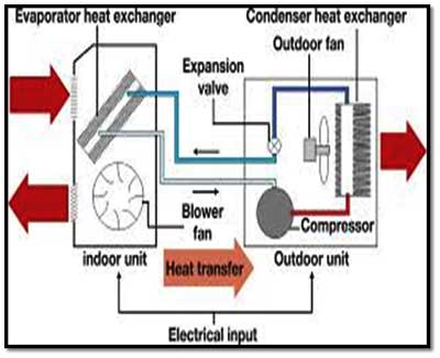
Fig.1.6. Schematic of open type air cycle refrigeration system
1.3.5. Steam Jet Refrigeration System:
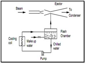
On the off chance that water is showered into a chamber where a low weight is kept up, an a piece of the water will vanish. The enthalpy of dissipation will cool the remaining water to its immersion temperature at the weight in the chamber. Clearly lower temperature will oblige lower weight. Water solidifies at 0°C henceforth temperature lower than 4°C can't be gotten with water. In this framework, high speed steam is utilized to entrain the vanishing water vapour. High-weight thought process steam passes through either concurrent or united disparate spout where it secures either sonic or supersonic speed or low weight of the request of 0.009 kPa relating to an evaporator temperature of 4°C. The high force of thought process steam entrains or conveys alongside it the water vapour vanishing from the glimmer chamber. Due to its high speed it moves the vapours against the weight angle up to the condenser where the weight is 5.6-7.4 kPa relating to condenser temperature of 35-45°C. The rationale vapour and the dissipated vapour both are dense and reused. This framework is known as steam plane refrigeration framework. Figure 1.7 demonstrates a schematic of the framework. This framework is determined by low- grade vitality that is methodology steam in substance plants.
In 1838, the Frenchman Pelletan was allowed a patent for the packing of steam by method for a plane of intention steam. Around 1900, the Englishman Charles Parsons contemplated the likelihood of lessening of weight by an entrainment impact from a steam plane. In any case, the credit for developing the steam plane refrigeration framework goes to the French engineer, Maurice Leblanc who added to the framework in 1907-08. In this framework, ejectors were utilized to create a high speed steam plane (˜ 1200 m/s). Taking into account Leblanc's outline the first business framework was made by Westinghouse in 1909 in Paris. Despite the fact that the productivity of the steam plane refrigeration framework was low, it was still appealing as water is innocuous and the framework can run utilizing fumes steam from a steam motor.
1.3.6. Thermoelectric Refrigeration Systems:
In 1821 German physicist T.J. See Beck reported that, when two intersections of divergent metals are kept at two separate temperatures, an electro rationale power (emf) is produced, bringing about stream of electric current. The emf delivered is discovered to be relative to temperature contrast. In 1834, a Frenchmen, J. Peltier watched the converse impact, i.e., cooling and warming of two intersections of disparate materials when direct present is passed through them, the high temperature exchange rate being corresponding to the current. In 1838, H.F.E. Lenz solidified a drop of water by the Peltier impact utilizing antimony and bismuth.
As per this when a current course through a conductor of a thermocouple that has a starting temperature inclination in it, then hotness exchange rate every unit length is relative to the result of current and the temperature. As the current course through thermoelectric material it gets warmed because of its electrical safety. This is known as the Joulean impact, further, conduction high temperature exchange from the hot intersection to the chilly intersection exchanges heat.
Both these hotness exchange rates must be remunerated by the Pettier Effect for some valuable cooling to be created. For quite a while, thermoelectric cooling taking into account the Pettier impact remained a research centre interest as the temperature contrast that could be gotten utilizing unadulterated metals was so little it was not possible be of any reasonable utilization. Protecting materials give poor thermoelectric execution due to their little electrical conductivity while metals are bad as a result of their expansive warm conductivity. Figure 1.8 demonstrates the schematic of the thermoelectric refrigeration framework in light of semiconductor materials. The Russian researcher, A. F. Ioffe is one of the pioneers in the range of thermoelectric refrigeration frameworks utilizing semiconductors.
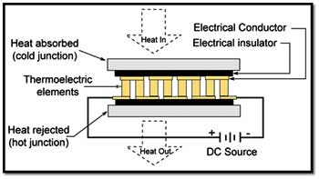
Fig.1.8. Schematic of a thermoelectric refrigeration system
Framework limits were regularly little because of poor effectiveness. However some extensive refrigeration limit frameworks, for example, a 3000 kcal/h ventilation system and a 6 ton limit cool stockpiling were additionally created. By utilizing multistage temperatures as low as –145oC were gotten. These frameworks because of their constrained execution (restricted by the materials) are presently utilized just as a part of certain corner applications, for example, electronic cooling, versatile coolers and so forth. Endeavours have additionally been made to club thermoelectric frameworks with photovoltaic cells with a perspective to create sun powered thermoelectric iceboxes.
1.3.7. Vortex tube:
In 1931, the French engineer Georges Ranque (1898-1973) found a fascinating wonder, which is called "Ranque impact" or "vortex impact". The tangential infusion of air into a round and hollow tube impels to quote his words "a giratory extension with concurrent generation of a break of hot air and a departure of cool air". Ranque was allowed a French patent in 1928 and a US patent in 1934 for this impact. Notwithstanding, the revelation was dismissed until after the second world war, when in 1945, Rudolph Hilsch, a German physicist, considered this impact and distributed a generally read exploratory paper on this gadget. Accordingly, the vortex tube has likewise been known as the "Ranque-Hilsch Tube". In spite of the fact that the productivity of this framework is low, it is exceptionally fascinating because of its mechanical effortlessness and moment cooling. It is advantageous where there is a supply of layered air.
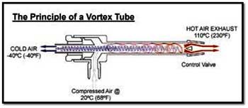
The present day vortex tube uses compacted air as a force source; it has no moving parts, and produces hot air from one end and frosty air from the other. The volume and temperature of these two airstreams are customizable with a valve incorporated with the hot air debilitate. Temperatures as low as -40°C and as high as 110°C are conceivable. Layered air is supplied to the vortex tube and passes through spouts that are tangential to an inside counter bore. These spouts set the air in a vortex movement. This turning stream of air turns 90° and passes down the hot tube as a turning shell, like a tornado. A valve toward one side of the tube permits a portion of the warmed air to escape. What does not escape, heads back up the tube as a second vortex inside the low-weight region of the bigger vortex. This inward vortex loses hotness and depletes through the flip side as cool air. At present vortex tube is utilized for spot cooling of machine parts, in electronic cooling furthermore in cooling coats for diggers.
- Describe refrigeration (Section 1.1)
- Present diverse trademark refrigeration schedules, specifically:
a. Usage of ice transported from colder areas (Section 1.2)
b. Usage of ice procured in winter and set away in ice houses (Section 1.2)
c. Usage of ice made by evening cooling (Section 1.2.1)
d. Usage of evaporative cooling (Section 1.2.2)
e. Cooling by salt game plans (Section 1.2.3)
- Present chronicled diverse re enacted refrigeration frameworks, particularly:
a. Vapour weight refrigeration structures, including
i. Nearby refrigeration structures (Section 1.3.1.1)
ii. Cooling structures (Section 1.3.1.2)
b. Vapour maintenance refrigeration structures (Section 1.3.2)
c. Sun based essentialness based refrigeration structures (Section 1.3.3)
d. Air cycle refrigeration structures (Section 1.3.4)
e. Steam and vapour plane refrigeration structures (Section 1.3.5)
f. Thermoelectric refrigeration structures (Section 1.3.6), and
g. Vortex tubes (Section 1.3.7)
1.1. Introduction
Refrigeration may be characterized as the procedure of accomplishing and keeping up a temperature underneath that of the surroundings, the point of being to cool some item or space to the obliged temperature. A standout amongst the most imperative applications of refrigeration has been the protection of perishable nourishment items by putting away them at low temperatures. Refrigeration frameworks are likewise utilized broadly for giving warm solace to individuals by method for cooling. Cooling alludes to the treatment of air to all the while control its temperature, dampness content, cleanliness, smell and course, as needed by inhabitants, a methodology, or items in the space. The historical backdrop of refrigeration is exceptionally intriguing following each part of it, the accessibility of refrigerants, the prime movers and the advancements in compressors and the systems for refrigeration all are a piece of it. The French researcher Roger Thývenot has composed a fabulous book on the historical backdrop of refrigeration all through the world.
1.2. Natural Refrigeration
In long time past days refrigeration was accomplished by common means, for example, the utilization of ice or evaporative cooling. In prior times, ice was either:
- Transported from colder regions,
- Harvested in winter and stored in ice houses for summer use or,
- Made during night by cooling of water by radiation to stratosphere.
In 1806, Frederic Tudor started the exchange ice by cutting it from the Hudson River and lakes of Massachusetts and sending out it to different nations including India. In India Tudor's ice was less expensive than the provincially made ice by nocturnal cooling. The ice exchange North America was a prospering business. Ice was transported to southern conditions of America in train compartments protected by 0.3 m of stopper protection. Exchanging ice was likewise famous in a few different nations, for example, Great Britain, Russia, Canada, Norway and France. In these nations ice was either transported from colder areas or was reaped in winter and put away in ice houses for utilization in summer. The ice exchange arrived at its crest in 1872 when America alone sent out 225000 tons of ice to different nations the extent that China and Australia. Notwithstanding, with the appearance of counterfeit refrigeration the ice exchange slowly declined.
1.2.1. Specialty of Ice making by Nocturnal Cooling:
The craft of making ice by nocturnal cooling was consummated in India. In this system ice was made by keeping a meagre layer of water in a shallow earthen tray, and after that presenting the tray to the night sky. Compacted feed of around 0.3 m thickness was utilized as protection. The water looses warm by radiation to the stratosphere, which is at around -55°C and by ahead of schedule morning hours the water in the trays stops to ice. This technique for ice creation was exceptionally prominent in India.
1.2.2. Evaporative Cooling:
As the name shows, evaporative cooling is the procedure of lessening the temperature of a framework by vanishing of water. Individuals sweat and disseminate their metabolic hotness by evaporative cooling if the surrounding temperature is more than skin temperature. Creatures, for example, the hippopotamus and wild ox cover themselves with mud for evaporative cooling. Evaporative cooling has been utilized as a part of India for a considerable length of time to get cool water in summer by putting away the water in earthen pots. The water saturates through the pores of earthen vessel to its external surface where it vanishes to the encompassing, engrossing its inert hotness to some extent from the vessel, which cools the water. Suitably spotted stacks in the rooms expanded the upward stream of warm air, which was supplanted by cool air. Evaporative cooling by putting wet straw tangles on the windows is additionally exceptionally regular in India. The straw mat produced using "khus" adds its inborn fragrance likewise to the air. Presently a-days desert coolers are being utilized as a part of hot and dry territories to give cooling in summer.
1.2.3. Cooling by Salt Solutions:
Certain substances, for example, regular salt, when added to water break down in water and retain its hotness of arrangement from water (endothermic procedure). This lessens the temperature of the arrangement (water+salt). Sodium Chloride salt (NaCl) can yield temperatures up to -20°C and Calcium Chloride (CaCl2) up to - 50°C in legitimately protected holders. In any case, as it is this procedure has constrained application, as the broke up salt must be recouped from its answer by warm in.
1.3. Artificial Refrigeration
Refrigeration as it is known nowadays is delivered by manufactured means. Despite the fact that it is exceptionally hard to make a reasonable outline in the middle of regular and manufactured refrigeration, it is by and large concurred that the historical backdrop of fake refrigeration started in the year 1755, when the Scottish educator William Cullen made the first refrigerating machine, which could deliver a little amount of ice in the lab. Taking into account the working standard, refrigeration frameworks can be named vapour squeezing frameworks, vapour ingestion frameworks, gas cycle frameworks and so on.
1.3.1. Vapour Compression Refrigeration Systems:
The premise of advanced refrigeration is the capacity of fluids to retain huge amounts of hotness as they bubble and dissipate. Educator William Cullen of the University of Edinburgh exhibited this in 1755 by putting some water in warm contact with ether under a beneficiary of a vacuum pump. The dissipation rate of ether expanded because of the vacuum pump and water could be solidified. This methodology includes two thermodynamic ideas, the vapour weight and the idle hotness. A fluid is in warm harmony with its own particular vapour at a weight called the immersion weight, which relies on upon the temperature alone.
In the event, that the weight is expanded for instance in a weight cooker, the water bubbles at higher temperature. The second idea is that the vanishing of fluid obliges inactive high temperature amid dissipation. On the off chance that idle high temperature is removed from the fluid, the fluid gets cooled. The temperature of ether will stay consistent the length of the vacuum pump keeps up a weight equivalent to immersion weight at the fancied temperature. This requires the evacuation of every last one of vapours shaped because of vaporization. In the event that a lower temperature is coveted, then a lower immersion weight will must be kept up by the vacuum pump. The segment of the cutting edge refrigeration framework where cooling is created by this technique is called evaporator.
Mechanical assembly depicted by Jacob Perkins in his patent detail of 1834. The refrigerant bubbles in evaporator B taking high temperature from encompassing water in holder A. The pump C draws vapour away and packs it to higher weight at which it can consolidate to fluids in tubes D, giving out high temperature to water in vessel E. Consolidated fluid moves through the weight stacked valve H, which keeps up the distinction of weight between the condenser and evaporator. The little pump above H is utilized for accusing the contraption of refrigerant.
John Hague made Perkins' outline into working model with a few changes. This Perkins machine is demonstrated in Fig.1.2. The most punctual vapour squeezing framework utilized either sulphuric (ethyl) or methyl ether. The American engineer Alexander Twining (1801-1884) got a British patent in 1850 for a vapour packing framework by utilization of ether, NH3 and CO2.
The man in charge of making a viable vapour layering refrigeration framework was James Harrison who took a patent in 1856 for a vapour packing framework utilizing ether, liquor or smelling salts. Charles Tellier of France licensed in 1864, refrigeration framework utilizing dimethyl ether which has a typical breaking point of -23.6
Fig.1.2. Perkins machine built by John Hague
Carl von Linde in Munich presented twofold acting alkali compressor. It obliged weights of more than 10 airs in the condenser. Since the typical breaking point of smelling salts is -33.3°C, vacuum was not needed on the low weight side. From that point forward alkali is utilized broadly as a part of expansive refrigeration plants.
1.3.1.1. Domestic refrigeration systems:
The household icebox utilizing regular ice (residential cooler) was designed in 1803 and was utilized for just about 150 years without much adjustment. The local cooler used to be made of wood with suitable protection. Ice used to be kept at the highest point of the crate, and low temperatures are created in the container because of high temperature exchange from ice by regular convection. A trickle skillet is utilized to gather the water shaped because of the softening of ice. The case must be recharged with new ice once all the ice dissolves.
In spite of the fact that the idea is very straightforward, the household refrigerator experienced a few impediments. The client needs to recharge the ice when it is devoured, and the most minimal temperatures that could be created inside the compartment are constrained.
General Electric Company presented the first residential icebox in 1911, took after via Frigidaire in 1915. Kelvinator dispatched the household mechanical cooler in 1918 in USA. In 1925, USA had around 25 million local iceboxes of which just 75000 were mechanical. Be that as it may, the assembling of household iceboxes became quickly, and by 1949 around 7 million residential coolers were delivered every year. With the generation volumes expanding the value fell pointedly (the cost was 600 dollars in 1920 and 155 dollars in 1940). The beginning household coolers utilized principally sulphur dioxide as refrigerant. A few units utilized methyl chloride and methylene chloride. These refrigerants were supplanted by Freon-12 in 1930s. In the first place these fridges were outfitted with open sort compressors determined by sash drive. General Electric Company presented the first icebox with a hermetic compressor in 1926. Before long the open sort compressors were totally supplanted by the hermetic compressors.
1.3.1.2. Air conditioning systems:
Refrigeration frameworks are likewise utilized for giving cooling and dehumidification in summer for individual solace (ventilating). The primary aerating and cooling frameworks were utilized for mechanical and in addition solace ventilating. Eastman Kodak introduced the first aerating and cooling framework in 1891 in Rochester, New York for the capacity of photographic movies. An aerating and cooling framework was introduced in a printing press in 1902 and in a phone trade in Hamburg in 1904. Numerous frameworks were introduced in tobacco and material production lines around 1900. The main local cooling framework was introduced in a house in Frankfurt in 1894. A private library in St Louis, USA was ventilated in 1895, and a clubhouse was aerated and cooled in Monte Carlo in 1901. Endeavours have likewise been made to aerate and cool traveller rail mentors utilizing ice.
Figure 1.3 demonstrates the essential parts of a vapour layering refrigeration framework. As indicated in the figure the essential framework comprises of an evaporator, compressor, condenser and an extension valve. The refrigeration impact is acquired exposed district as hotness is removed by the vaporization of refrigerant in the evaporator. The refrigerant vapour from the evaporator is layered in the compressor to a high weight at which its immersion temperature is more noteworthy than the encompassing or some other hotness sink. Consequently when the high weight, high temperature refrigerant moves through the condenser, build up of the vapour into fluid happens by hotness dismissal to the high temperature sink. To finish the cycle, the high weight fluid is made to course through a development valve. In the development valve the weight and temperature of the refrigerant diminishing. This low weight and low temperature refrigerant vapor vanishes in the evaporator taking hotness from the frosty locale. It ought to be watched that the framework works on a shut cycle. The framework obliges enter as mechanical work. It concentrates heat from a chilly space and rejects hotness to a high temperature high temperature sink.
Fig.1.3. Schematic of a basic vapour compression refrigeration system
A refrigeration framework can likewise be utilized as a hotness pump, in which the helpful yield is the high temperature hotness rejected at the condenser. Then again, a refrigeration framework can be utilized for giving cooling as a part of summer and warming in winter. Such frameworks have been manufactured and are accessible now.
1.3.2. Vapour Absorption Refrigeration Systems:
John Leslie in 1810 kept H2SO4 and water in two different containers joined together. H2SO4 has high fondness for water. It assimilates water vapour and this turns into the rule of evacuating the vanished water vapour obliging no compressor or pump. H2SO4 is a permeable in this framework that must be reused by warming to dispose of the consumed water vapour, for consistent operation. Windhausen in 1878 utilized this rule for retention refrigeration framework, which took a shot at H2SO4. Ferdinand Carre designed water alkali ingestion framework in 1860. Water is a solid retentive of NH3. In the event that NH3 is kept in a vessel that is presented to an alternate vessel containing water, the solid assimilation capability of water will result in dissipation of NH3 obliging no compressor to drive the vapours.
Fig.1.5 Schematic diagram of a fluid vapour absorption refrigeration system
An alternate variety of vapour assimilation framework is the one taking into account Lithium bromide-water. This framework is utilized for chilled water cooling framework. This is a descendent of Windhausen's machine with LiBr supplanting H2SO4. In this framework LiBr is the permeable and water is the refrigerant. This framework meets expectations at vacuum weights. The condenser and the generator are housed in one round and hollow vessel and the evaporator and the safeguard are housed in second vessel. This additionally runs on second rate vitality obliging a kettle or procedure steam.
1.3.3. Solar Energy based Refrigeration System:
Endeavours have been made to run vapour ingestion framework by sun oriented vitality with concentrating and level plate sun based gatherers. A few little sun oriented assimilation refrigeration frameworks have been made around 1950s in a few nations. Teacher G.O.G. L??f of America is one of the pioneers in the range of sunlight based refrigeration utilizing level plate gatherers. A sun based refrigeration framework that could deliver 250 kg of ice every day was introduced in Tashkent, USSR in 1953. This framework utilized an allegorical mirror of 10 m2 territory for concentrating the sunlight based radiation. F. Trombe introduced an ingestion machine with a cylinder-allegorical mirror of 20 m2 at Monologues, France, which delivered 100 kg of ice every day.
Genuine thought to sun oriented refrigeration framework was given since 1965, because of the lack of fossil fuel based vitality sources. LiBr-water based frameworks have been produced for cooling purposes. The primary sunlight based ventilating framework was introduced in a trial sun oriented house in University of Queensland, Australia in 1966. After this few frameworks in view of sunlight based vitality were inherent numerous parts of the world including India. In 1976, there were around 500 sun oriented retention frameworks in USA alone. Pretty much all these were in view of LiBr-water as these frameworks don't require high warming temperatures. These frameworks were for the most part utilized for space ventilating. Irregular ingestion framework in light of sun powered vitality have additionally been constructed and worked effectively. In these frameworks, the cooling impact is gotten amid the evening, while the framework gets "charged" amid the day utilizing sun based vitality. Despite the fact that the effectiveness of these frameworks is somewhat poor obliging sunlight based authority region, they may discover applications in remote and provincial territories where space is not an imperative. Likewise, these frameworks are environment benevolent as they utilize eco-accommodating refrigerants and run on clean and renewable sun based vitality.
1.3.4. Gas Cycle Refrigeration:
On the off chance that air at high weight develops and does work (say moves a barrel or turns a turbine), its temperature will lessen. This is eluded to man as right on time as the eighteenth century. Dalton and Gay Lusaac considered this in 1807. Sadi Carnot said this as an astounding sensation in 1824. Regardless, Dr. John Gorrie a specialist in Florida developed one such machine in 1844 to make ice for the facilitating of his patients encountering fever. This machine used pressed air at 2 atm. weight and conveyed bitter water at a temperature of –7oC, which was then used to make ice. Alexander Carnegie Kirk in 1862 made an air cycle cooling machine. This structure used steam engine to run its compressor. Using a crushing level of 6 to 8, Kirk could make temperatures as low as ??40oC. Paul Gifford in 1875 consummated the open sort of machine. This machine was further upgraded by T B Lightfoot, A Haslam, Henry Bell and James Coleman. This was the guideline strategy for marine refrigeration for a long while.
Blunt Allen in New York developed a close cycle machine using high weights to reduce the volume stream rates. This was named thick air machine. These days air cycle refrigeration is used pretty much as a piece of carriers whose turbo compressor can manage significant volume stream rates. Figure 1.6 exhibits the schematic of an open sort air cycle refrigeration structure. The key system demonstrated here contains a compressor, an expander and a hotness exchanger. Air from the frigid room is layered in the compressor. The hot and high weight air rejects hotness to the high temperature sink (cooling water) in the hotness exchanger. The warm yet high weight air stretches out in the expander. The chilly air after expansion is sent to the cool space for giving cooling. The work of improvement not completely reimburses the work of layering; from this time forward both the expander and the compressor are mounted on a run of the mil.
Fig.1.6. Schematic of open type air cycle refrigeration system
1.3.5. Steam Jet Refrigeration System:
On the off chance that water is showered into a chamber where a low weight is kept up, an a piece of the water will vanish. The enthalpy of dissipation will cool the remaining water to its immersion temperature at the weight in the chamber. Clearly lower temperature will oblige lower weight. Water solidifies at 0°C henceforth temperature lower than 4°C can't be gotten with water. In this framework, high speed steam is utilized to entrain the vanishing water vapour. High-weight thought process steam passes through either concurrent or united disparate spout where it secures either sonic or supersonic speed or low weight of the request of 0.009 kPa relating to an evaporator temperature of 4°C. The high force of thought process steam entrains or conveys alongside it the water vapour vanishing from the glimmer chamber. Due to its high speed it moves the vapours against the weight angle up to the condenser where the weight is 5.6-7.4 kPa relating to condenser temperature of 35-45°C. The rationale vapour and the dissipated vapour both are dense and reused. This framework is known as steam plane refrigeration framework. Figure 1.7 demonstrates a schematic of the framework. This framework is determined by low- grade vitality that is methodology steam in substance plants.
In 1838, the Frenchman Pelletan was allowed a patent for the packing of steam by method for a plane of intention steam. Around 1900, the Englishman Charles Parsons contemplated the likelihood of lessening of weight by an entrainment impact from a steam plane. In any case, the credit for developing the steam plane refrigeration framework goes to the French engineer, Maurice Leblanc who added to the framework in 1907-08. In this framework, ejectors were utilized to create a high speed steam plane (˜ 1200 m/s). Taking into account Leblanc's outline the first business framework was made by Westinghouse in 1909 in Paris. Despite the fact that the productivity of the steam plane refrigeration framework was low, it was still appealing as water is innocuous and the framework can run utilizing fumes steam from a steam motor.
1.3.6. Thermoelectric Refrigeration Systems:
In 1821 German physicist T.J. See Beck reported that, when two intersections of divergent metals are kept at two separate temperatures, an electro rationale power (emf) is produced, bringing about stream of electric current. The emf delivered is discovered to be relative to temperature contrast. In 1834, a Frenchmen, J. Peltier watched the converse impact, i.e., cooling and warming of two intersections of disparate materials when direct present is passed through them, the high temperature exchange rate being corresponding to the current. In 1838, H.F.E. Lenz solidified a drop of water by the Peltier impact utilizing antimony and bismuth.
As per this when a current course through a conductor of a thermocouple that has a starting temperature inclination in it, then hotness exchange rate every unit length is relative to the result of current and the temperature. As the current course through thermoelectric material it gets warmed because of its electrical safety. This is known as the Joulean impact, further, conduction high temperature exchange from the hot intersection to the chilly intersection exchanges heat.
Both these hotness exchange rates must be remunerated by the Pettier Effect for some valuable cooling to be created. For quite a while, thermoelectric cooling taking into account the Pettier impact remained a research centre interest as the temperature contrast that could be gotten utilizing unadulterated metals was so little it was not possible be of any reasonable utilization. Protecting materials give poor thermoelectric execution due to their little electrical conductivity while metals are bad as a result of their expansive warm conductivity. Figure 1.8 demonstrates the schematic of the thermoelectric refrigeration framework in light of semiconductor materials. The Russian researcher, A. F. Ioffe is one of the pioneers in the range of thermoelectric refrigeration frameworks utilizing semiconductors.
Fig.1.8. Schematic of a thermoelectric refrigeration system
Framework limits were regularly little because of poor effectiveness. However some extensive refrigeration limit frameworks, for example, a 3000 kcal/h ventilation system and a 6 ton limit cool stockpiling were additionally created. By utilizing multistage temperatures as low as –145oC were gotten. These frameworks because of their constrained execution (restricted by the materials) are presently utilized just as a part of certain corner applications, for example, electronic cooling, versatile coolers and so forth. Endeavours have additionally been made to club thermoelectric frameworks with photovoltaic cells with a perspective to create sun powered thermoelectric iceboxes.
1.3.7. Vortex tube:
In 1931, the French engineer Georges Ranque (1898-1973) found a fascinating wonder, which is called "Ranque impact" or "vortex impact". The tangential infusion of air into a round and hollow tube impels to quote his words "a giratory extension with concurrent generation of a break of hot air and a departure of cool air". Ranque was allowed a French patent in 1928 and a US patent in 1934 for this impact. Notwithstanding, the revelation was dismissed until after the second world war, when in 1945, Rudolph Hilsch, a German physicist, considered this impact and distributed a generally read exploratory paper on this gadget. Accordingly, the vortex tube has likewise been known as the "Ranque-Hilsch Tube". In spite of the fact that the productivity of this framework is low, it is exceptionally fascinating because of its mechanical effortlessness and moment cooling. It is advantageous where there is a supply of layered air.
The present day vortex tube uses compacted air as a force source; it has no moving parts, and produces hot air from one end and frosty air from the other. The volume and temperature of these two airstreams are customizable with a valve incorporated with the hot air debilitate. Temperatures as low as -40°C and as high as 110°C are conceivable. Layered air is supplied to the vortex tube and passes through spouts that are tangential to an inside counter bore. These spouts set the air in a vortex movement. This turning stream of air turns 90° and passes down the hot tube as a turning shell, like a tornado. A valve toward one side of the tube permits a portion of the warmed air to escape. What does not escape, heads back up the tube as a second vortex inside the low-weight region of the bigger vortex. This inward vortex loses hotness and depletes through the flip side as cool air. At present vortex tube is utilized for spot cooling of machine parts, in electronic cooling furthermore in cooling coats for diggers.
Published date : 16 Feb 2015 02:34PM