

Sakshi Education
Introduction:
With the passage of time, technology has merged itself with the daily life of humans. We have seen so much progress in the field of science and technology but we are not able to make full use of it. One such area for improvement is the Electricity board (EB) billing system. Our existing electricity board billing system in India is obsolete and time consuming. We are proposing a system through which electricity billing becomes fully automated and communication is made possible via GSM networks. In EB meters there are two types, Analog meters and digital meters. The Analog meters were mostly used in olden days. These meter readings are calculated under the basis of the number of rotation made by the rotating disc. The digital meter is the mostly used EB meters now a day. This meter works on the basis of the flash made by the LED and according to that the reading are calculated. In our system the central EB office has immediate access to all consumer homes in a locality with the help of GSM system.
The EB meter present in each house is connected by wireless network through a GSM modem with the Electricity Board office and also the home user is provided with a Zigbee network in which one Zigbee is connected to the Microcontroller and the other Zigbee module is connected to the home user Personal Computer for timely viewing of the reading consumed by his household and also provides a provision of knowing the individual energy consumption by each device used in our homes.
In this article we will learn what is GSM modem and Energy meter and see how to interface these devices to Arduino.
The Components required:
Description:
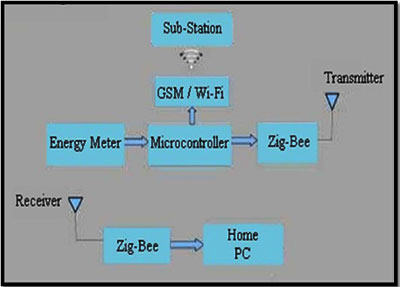
The design of a simple low cost wireless GSM and Zigbee based energy meter and its associated interface, for automating billing and managing the collected data globally. This system replaces traditional meter reading methods and enables remote access of existing energy meter by the energy provider. Also they can monitor the meter readings regularly without the person visiting each house. A GSM and Zigbee based wireless communication modules are integrated with electronic energy meter of each entity to have remote access over the usage of electricity. A PC with a Zigbee receiver at the other end, which contains the database acts as the home section point where the domestic user can have a track of how much amount of Energy is consumed and hence the amount to be paid is shown in software called X-CTU. Subsequently the amount of energy consumed and also the related bill is sent to the Sub-station where the track of energy consumed and the amount of money to be paid is maintained. Live meter reading from the GSM enabled energy meter is sent back to this billing point periodically and these details are updated in a central database.
Figure1: Block diagram of Wireless Energy Meter
Global System for Mobile (GSM)
Global System for Mobile Communications (GSM) modems are specialized types of modems that operate over subscription based wireless networks, similar to a mobile phone. A GSM modem accepts a Subscriber Identity Module (SIM) card, and basically acts like a mobile phone for a computer. Such a modem can even be a dedicated mobile phone that the computer uses for GSM network capabilities. Traditional modems are attached to computers to allow dial-up connections to other computer systems. A GSM modem operates in a similar fashion, except that it sends and receives data through radio waves rather than a telephone line. This type of modem may be an external device connected via a Universal Serial Bus (USB) cable or a serial cable. More commonly, however, it is a small device that plugs directly into the USB port or card slot on a computer or laptop. GSM is an open and digital cellular technology used for transmitting mobile voice and data services operates at the 850MHz, 900MHz, 1800MHz and 1900MHz frequency bands.
Features:
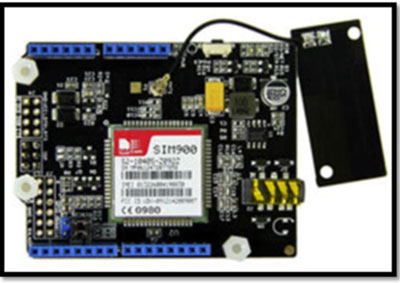
Figure2: GSM Modem Shield
Specifications of the GSM modem Shield
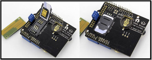
Figure3: SIM card slot in GSM Shield
Power Requirements of the GPRS Shield:
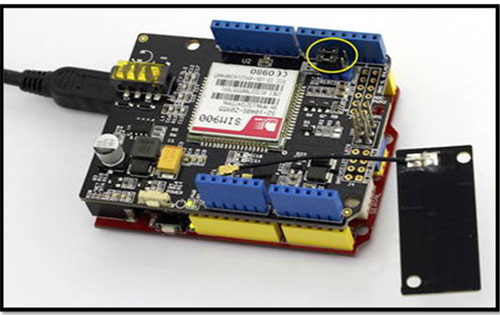
Figure4: GSM shield is connected to Arduino
Like a GSM mobile phone, a GSM modem requires a SIM card from a wireless carrier in order to operate. AT commands are used to control modems. Both GSM modems and dial-up modems support a common set of standard AT commands. You can use a GSM modem just like a dial-up modem. In addition to the standard AT commands, GSM modems support an extended set of AT commands.
These extended AT commands are defined in the GSM standards. With the extended AT commands, you can do things like:
Energy Meter
An electricity meter or energy meter is a device that measures the amount of electric energy consumed by a residence, business, or an electrically powered device. Electricity meters are typically calibrated in billing units, the most common one being the kilowatt hour. A periodic reading of electric meters establishes billing cycles and energy used during a cycle. In some areas the electric rates are higher during certain times of day, reflecting the higher cost of power resources during peak demand time periods. Electric utilities use electric meters installed at customers’ premises to measure electric energy delivered to their customers for billing purposes. They are typically calibrated in billing units, the most common one being the kilowatt hour. They are usually read once each billing period. In settings when energy savings during certain periods are desired, meters may measure demand, the maximum use of power in some interval. "Time of day" metering allows electric rates to be changed during a day, to record usage during peak high-cost periods and off-peak, lower-cost, periods.
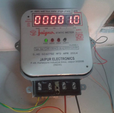
Figure5: Energy Meter
Components Interfacing:
The system has the Arduino Uno Microcontroller as Central Processing Unit. The whole system is interfaced with Arduino. The GSM shield (modem) is serially connected with the controller which is the major communication module between user and Electricity provider. The GSM uses its own network for the transfer of information. Also the Zigbee Shield is connected to the two Software Serial pins which are Rx (pin 0) and Tx (pin 1) which provides serial connection between Arduino and the Zigbee Shield for the transmission of data to the home user PC for him/her to monitor the Power usage and the amount to be paid at any time during the entire month. The embedded C programming is used for programming Arduino using Arduino IDE software. The programming makes use of messaging features of GSM command and the Serial Print which prints the data to the serial pins which are connected to the Zigbee Shield. The power to the Arduino Uno is provided by the power adapter of the rating of 9V, 1A, this high current power adapter is required for the smooth operation of the circuitry because the Arduino GSM shield draws a current of 0.7A – 1A when used of calling and messaging operations. The Microprocessor based system continuously records the live energy meter readings and can be sent to the Electricity department on request. A dedicated GSM modem with SIM card is required for each energy meter.
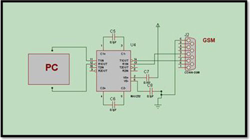
Figure6: Circuit diagram
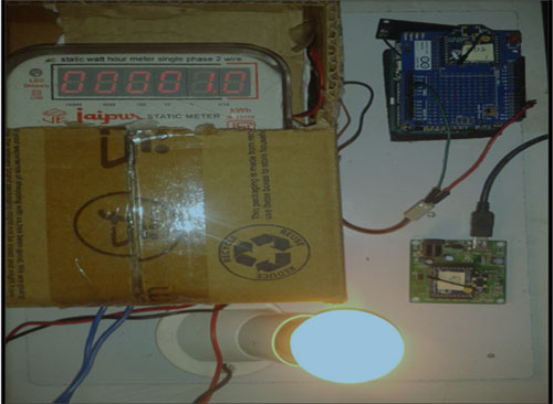
Figure7: Energy Meter
Program:
#include
#include
SoftwareSerial mySerial(7, 8);
void setup()
{
mySerial.begin(19200); // gsm baud rate
//Serial.begin(19200);
// XBee.begin(9600); //zigbee baud rate
Serial.begin(9600);
delay(500);
}
void loop()
{
int sensorValue=analogRead(A1);
if (mySerial.available())
Serial.write(mySerial.read());
mySerial.print("AT+CMGF=1\r"); //Because we want to send the SMS in text mode
delay(100);
mySerial.println("AT + CMGS = \"+919949687970\"");//send sms message, be careful need to
//add a country code before the cell phone number
delay(100);
mySerial.println("The current reading is:");
mySerial.println(sensorValue*0.4887); //the content of the message
delay(100);
mySerial.println((char)26); //the ASCII code of the ctrl+z is 26
delay(100);
mySerial.println();
delay(1000);
Serial.print(sensorValue*0.4887);
Serial.println("^C");
//}
}
Output:
The current meter reading is sent to the given mobile number “+919949687970”.
With the passage of time, technology has merged itself with the daily life of humans. We have seen so much progress in the field of science and technology but we are not able to make full use of it. One such area for improvement is the Electricity board (EB) billing system. Our existing electricity board billing system in India is obsolete and time consuming. We are proposing a system through which electricity billing becomes fully automated and communication is made possible via GSM networks. In EB meters there are two types, Analog meters and digital meters. The Analog meters were mostly used in olden days. These meter readings are calculated under the basis of the number of rotation made by the rotating disc. The digital meter is the mostly used EB meters now a day. This meter works on the basis of the flash made by the LED and according to that the reading are calculated. In our system the central EB office has immediate access to all consumer homes in a locality with the help of GSM system.
The EB meter present in each house is connected by wireless network through a GSM modem with the Electricity Board office and also the home user is provided with a Zigbee network in which one Zigbee is connected to the Microcontroller and the other Zigbee module is connected to the home user Personal Computer for timely viewing of the reading consumed by his household and also provides a provision of knowing the individual energy consumption by each device used in our homes.
In this article we will learn what is GSM modem and Energy meter and see how to interface these devices to Arduino.
The Components required:
- Arduino uno board with cable,
- Zigbee modules and Zigbee wireless shield,
- GSM Shield,
- Energy Meter
- Bread board with jumpers
Description:
The design of a simple low cost wireless GSM and Zigbee based energy meter and its associated interface, for automating billing and managing the collected data globally. This system replaces traditional meter reading methods and enables remote access of existing energy meter by the energy provider. Also they can monitor the meter readings regularly without the person visiting each house. A GSM and Zigbee based wireless communication modules are integrated with electronic energy meter of each entity to have remote access over the usage of electricity. A PC with a Zigbee receiver at the other end, which contains the database acts as the home section point where the domestic user can have a track of how much amount of Energy is consumed and hence the amount to be paid is shown in software called X-CTU. Subsequently the amount of energy consumed and also the related bill is sent to the Sub-station where the track of energy consumed and the amount of money to be paid is maintained. Live meter reading from the GSM enabled energy meter is sent back to this billing point periodically and these details are updated in a central database.
Figure1: Block diagram of Wireless Energy Meter
Global System for Mobile (GSM)
Global System for Mobile Communications (GSM) modems are specialized types of modems that operate over subscription based wireless networks, similar to a mobile phone. A GSM modem accepts a Subscriber Identity Module (SIM) card, and basically acts like a mobile phone for a computer. Such a modem can even be a dedicated mobile phone that the computer uses for GSM network capabilities. Traditional modems are attached to computers to allow dial-up connections to other computer systems. A GSM modem operates in a similar fashion, except that it sends and receives data through radio waves rather than a telephone line. This type of modem may be an external device connected via a Universal Serial Bus (USB) cable or a serial cable. More commonly, however, it is a small device that plugs directly into the USB port or card slot on a computer or laptop. GSM is an open and digital cellular technology used for transmitting mobile voice and data services operates at the 850MHz, 900MHz, 1800MHz and 1900MHz frequency bands.
Features:
- Improved spectrum efficiency
- International roaming
- Compatibility with integrated services digital network (ISDN)
- Support for new services
- SIM phonebook management
- Fixed dialing number (FDN)
- Real time clock with alarm management
- High-quality speech
- Uses encryption to make phone calls more secure
- Short message service (SMS)
Figure2: GSM Modem Shield
Specifications of the GSM modem Shield
- The Shield has a SIM900 GSM Modem on it.
- The Operating voltage is in between 6 – 12V.
- It is provided with a 2-in-1 Headset jack for calling purpose.
- The antenna is a PCB antenna.
- It is provided with a SIM card slot at the back.
- It has an ON/ OFF switch.
Figure3: SIM card slot in GSM Shield
Power Requirements of the GPRS Shield:
- The GPRS/ GSM shield normally operates with currents from 700mA – 1000mA when powered externally.
- When working with the GPRS services, the Modem may pull up a circuit of nearly 2000mA.
- The best way to power the Shield is through a 1A adapter for continuous operation of the shield.
- The Shield cannot work with just power supplied from the USB of the PC.
Figure4: GSM shield is connected to Arduino
Like a GSM mobile phone, a GSM modem requires a SIM card from a wireless carrier in order to operate. AT commands are used to control modems. Both GSM modems and dial-up modems support a common set of standard AT commands. You can use a GSM modem just like a dial-up modem. In addition to the standard AT commands, GSM modems support an extended set of AT commands.
These extended AT commands are defined in the GSM standards. With the extended AT commands, you can do things like:
- Reading, writing and deleting SMS messages.
- Sending SMS messages.
- Monitoring the signal strength.
- Monitoring the charging status and charge level of the battery.
- Reading, writing and searching phone book entries.
Energy Meter
An electricity meter or energy meter is a device that measures the amount of electric energy consumed by a residence, business, or an electrically powered device. Electricity meters are typically calibrated in billing units, the most common one being the kilowatt hour. A periodic reading of electric meters establishes billing cycles and energy used during a cycle. In some areas the electric rates are higher during certain times of day, reflecting the higher cost of power resources during peak demand time periods. Electric utilities use electric meters installed at customers’ premises to measure electric energy delivered to their customers for billing purposes. They are typically calibrated in billing units, the most common one being the kilowatt hour. They are usually read once each billing period. In settings when energy savings during certain periods are desired, meters may measure demand, the maximum use of power in some interval. "Time of day" metering allows electric rates to be changed during a day, to record usage during peak high-cost periods and off-peak, lower-cost, periods.
Figure5: Energy Meter
Components Interfacing:
The system has the Arduino Uno Microcontroller as Central Processing Unit. The whole system is interfaced with Arduino. The GSM shield (modem) is serially connected with the controller which is the major communication module between user and Electricity provider. The GSM uses its own network for the transfer of information. Also the Zigbee Shield is connected to the two Software Serial pins which are Rx (pin 0) and Tx (pin 1) which provides serial connection between Arduino and the Zigbee Shield for the transmission of data to the home user PC for him/her to monitor the Power usage and the amount to be paid at any time during the entire month. The embedded C programming is used for programming Arduino using Arduino IDE software. The programming makes use of messaging features of GSM command and the Serial Print which prints the data to the serial pins which are connected to the Zigbee Shield. The power to the Arduino Uno is provided by the power adapter of the rating of 9V, 1A, this high current power adapter is required for the smooth operation of the circuitry because the Arduino GSM shield draws a current of 0.7A – 1A when used of calling and messaging operations. The Microprocessor based system continuously records the live energy meter readings and can be sent to the Electricity department on request. A dedicated GSM modem with SIM card is required for each energy meter.
Figure6: Circuit diagram
Figure7: Energy Meter
Program:
#include
#include
SoftwareSerial mySerial(7, 8);
void setup()
{
mySerial.begin(19200); // gsm baud rate
//Serial.begin(19200);
// XBee.begin(9600); //zigbee baud rate
Serial.begin(9600);
delay(500);
}
void loop()
{
int sensorValue=analogRead(A1);
if (mySerial.available())
Serial.write(mySerial.read());
mySerial.print("AT+CMGF=1\r"); //Because we want to send the SMS in text mode
delay(100);
mySerial.println("AT + CMGS = \"+919949687970\"");//send sms message, be careful need to
//add a country code before the cell phone number
delay(100);
mySerial.println("The current reading is:");
mySerial.println(sensorValue*0.4887); //the content of the message
delay(100);
mySerial.println((char)26); //the ASCII code of the ctrl+z is 26
delay(100);
mySerial.println();
delay(1000);
Serial.print(sensorValue*0.4887);
Serial.println("^C");
//}
}
Output:
The current meter reading is sent to the given mobile number “+919949687970”.
Published date : 22 May 2015 12:06PM