

Sakshi Education
In this article we going to learn how to interface Zigbee to Arduino and sense the data from sensors and transmits wirelessly to other device using Zigbee technology, that is acquire the analog data from environment and transmit this from source node to sink node.
Description:
The Sensors at the sensor node continuously monitors the phenomenon in the targeted area and sensed signals are being passed to the processing element for further processing, in our case it is Arduino (ATMEGA328 Microcontroller). These processed values are further transmitted over a wireless medium to the sink node or Base station with the help of Zigbee Modules. At the other end that is sink node the Zigbee collects the data and transmits to PC.
In simple words we will interface a Zigbee module with the Arduino Uno and the temperature readings from the LM35 sensor will be forwarded to the other PC wirelessly through the Zigbee.
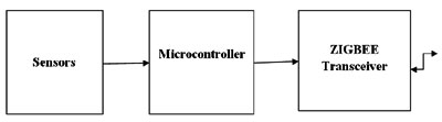
Sensor node/End device:
Sensors Microcontroller ZIGBEE Transceiver
Sink nodes/Coordinator/Base station:
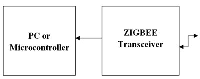
PC or Microcontroller ZIGBEE Transceiver
LM35 Temperature sensor:
The LM35 series temperature sensors are precision integrated-circuit temperature sensors, whose output voltage is linearly proportional to the Celsius (Centigrade) temperature. The LM35 has advantages over other linear temperature sensors calibrated in degrees kelvin. No need to provide any external calibration or trimming for the sensor. Thus ensures easy operation. The other advantage of this sensor is its body itself acts as sensor. The accuracy of the sensor is 0.5 degree at 25 degree centigrade. The LM35 Temperature sensor pin configuration details as shown in Figure1.
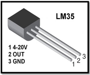
Figure1: LM35 Temperature sensor
Zigbee Module:
Zigbee is wireless technology defined by IEEE 802.15.4 Personal Area Network standard. It is primarily designed for the wide range controlling applications and to replace the existing non-standard technologies. It currently operates in 868 MHz band at a data rate of 20Kbps in Europe, 914MHz band at 40kbps in USA, and the 2.4GHz ISM bands Worldwide at a maximum data-rate of 250kbps. One of the main advantages of this ZIGBEE communication is that it provides a noise free communication, the amount of noise added in this type of communication is very less compared to the other wireless communications.
The Zigbee modules further divided into two categories. They are Zigbee (Xbee) and the other is Zigbee pro(Xbee Pro). The Pro series features improvements in both range and power management. Due to these features, these modules have been chosen for the wireless communication component in the system.
Operation:
The Sensing element continuously monitors the phenomenon in the targeted area, in our case either forests or buildings and then the sensed signals are being passed to the processing element for further processing, in our case it is AVR Microcontroller. These processed values are further transmitted over a wireless medium to the sink node or Base station with the help of Zigbee Modules. Thus each node, part of the whole network will transmit the data over wireless medium to the sink node or Base station. The whole network is implemented using Star and Mesh topologies. Star topology is used to transmit the data from the sensor nodes to the sink nodes. Mesh topology has been used to transmit the data from the sink nodes or cluster heads to the Base station. i.e. Sensor nodes dump the data into sink node called cluster head, which is in the range of sensor node. Then the cluster nodes transmit the data to the other cluster heads nearby for passing the information to the Base station.
In a mesh network, ZigBee, devices have one of three different duties:
Description:
The Sensors at the sensor node continuously monitors the phenomenon in the targeted area and sensed signals are being passed to the processing element for further processing, in our case it is Arduino (ATMEGA328 Microcontroller). These processed values are further transmitted over a wireless medium to the sink node or Base station with the help of Zigbee Modules. At the other end that is sink node the Zigbee collects the data and transmits to PC.
In simple words we will interface a Zigbee module with the Arduino Uno and the temperature readings from the LM35 sensor will be forwarded to the other PC wirelessly through the Zigbee.
Sensor node/End device:
Sensors Microcontroller ZIGBEE Transceiver
Sink nodes/Coordinator/Base station:
PC or Microcontroller ZIGBEE Transceiver
LM35 Temperature sensor:
The LM35 series temperature sensors are precision integrated-circuit temperature sensors, whose output voltage is linearly proportional to the Celsius (Centigrade) temperature. The LM35 has advantages over other linear temperature sensors calibrated in degrees kelvin. No need to provide any external calibration or trimming for the sensor. Thus ensures easy operation. The other advantage of this sensor is its body itself acts as sensor. The accuracy of the sensor is 0.5 degree at 25 degree centigrade. The LM35 Temperature sensor pin configuration details as shown in Figure1.
Figure1: LM35 Temperature sensor
Zigbee Module:
Zigbee is wireless technology defined by IEEE 802.15.4 Personal Area Network standard. It is primarily designed for the wide range controlling applications and to replace the existing non-standard technologies. It currently operates in 868 MHz band at a data rate of 20Kbps in Europe, 914MHz band at 40kbps in USA, and the 2.4GHz ISM bands Worldwide at a maximum data-rate of 250kbps. One of the main advantages of this ZIGBEE communication is that it provides a noise free communication, the amount of noise added in this type of communication is very less compared to the other wireless communications.
The Zigbee modules further divided into two categories. They are Zigbee (Xbee) and the other is Zigbee pro(Xbee Pro). The Pro series features improvements in both range and power management. Due to these features, these modules have been chosen for the wireless communication component in the system.
Operation:
The Sensing element continuously monitors the phenomenon in the targeted area, in our case either forests or buildings and then the sensed signals are being passed to the processing element for further processing, in our case it is AVR Microcontroller. These processed values are further transmitted over a wireless medium to the sink node or Base station with the help of Zigbee Modules. Thus each node, part of the whole network will transmit the data over wireless medium to the sink node or Base station. The whole network is implemented using Star and Mesh topologies. Star topology is used to transmit the data from the sensor nodes to the sink nodes. Mesh topology has been used to transmit the data from the sink nodes or cluster heads to the Base station. i.e. Sensor nodes dump the data into sink node called cluster head, which is in the range of sensor node. Then the cluster nodes transmit the data to the other cluster heads nearby for passing the information to the Base station.
In a mesh network, ZigBee, devices have one of three different duties:
- Coordinator: Establishes and maintains the network by assigning addresses to joining (associated) devices and assisting with path planning form various nodes to its self. In our case base station.
- Routers: move data between nodes that cannot communicate directly. In our case sink nodes or cluster heads.
- End devices: The node that collects data and controls devices on the network and is typically connected to our controllers, sensors and other devices for network interfacing.
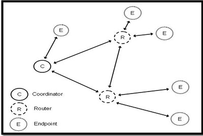
Figure2: Nodes in a Mesh Network
Null Modem Serial Cable (RS-232 Interface)
In order to transmit the sensor output to the Zigbee Module a serial communications link must be established. This can be done by using the supplied null modem. Alternatively, a null modem cable can be easily constructed with two DB-9 male connectors by following the pin out in Figure4.
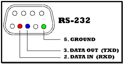
Figure3: Null Modem Cable Construction
- Connect pin 5 (ground) from one header to pin 5 of the other header via wire wrapping or soldering.
- Connect pin 2 (in) of header 1 to Pin 3 (out) of header 2 via wire wrapping or soldering.
- Connect pin 3 (out) of header 1 to pin 2 (in) of header 2 via wire wrapping or soldering.
Zigbee pin-configuration
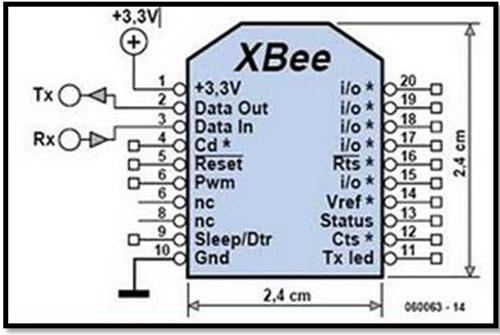
Figure4: Pin configuration
The components required for this project are
- Arduion Uno Board with USB cable
- Bread Board with jumpers cables
- LM35 Temperature sensor
- Zigbee series2 modules two number
- USB Interface Board (for interfacing between an RF module & host PC).
Circuit Diagram:
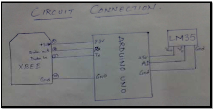
Figure5: Circuit Diagram
Program:
First we will write a code for the same in Arduino IDE platform, compile it and then debug the code into the micro-controller.
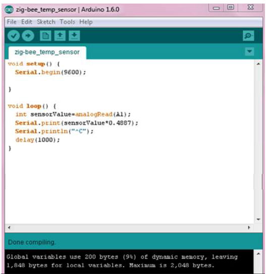
Figure6: Program
Program Explanation:
- Void setup (): This part of the program consists of the code which is executed only once. Like pin initialization, button initialization etc.
- Serial.begin(9600);
Syntax: Serial.begin(baud rate);
This statement is used for setting the bits transmission between the PC and Arduino at an equal rate. Generally the Arduino operates at baud rate of 9600 bps.
- Void loop(): This part of the code is to be repeated continuously.
- int sensorvalue=analogRead(A1);
Here we define a variable “sensorvalue” whose value is the Analog input at the pin
“A1”. This analog input is the value in millivolts.
- Serial.print(sensorvalue * 0.4887);
This “Serial.print( statement) “ prints the statement or value pointed by the statement
in the serial console.
Note: since we get the temperature sensor output in millivolts to convert it into degree
Celsius we use the following formula:
Value in degree Celsius = value in millivolts * (500 / 1023).
- Serial.println: this function is for new line.
Serial.println(“message”) prints the message and then goes to new line.
- delay(1000) :
Syntax: delay( time in milliseconds);
The below figure shows an LM35 temperature sensor and Zigbee module is connected to Arduino Uno. The output of the temperature value will be displayed at the other Zigbee module connected to PC.
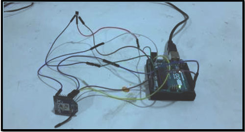
Figure7: LM35 Temperature and Zigbee Connected to Arduino
Published date : 21 May 2015 06:01PM