

Sakshi Education
The project Web based service to monitor water leak in the pipeline using Arduino is the one which is used to detect a leak, which results in a large wastage of water flowing through water pipelines. This causes a great damage to the public of many regions. As water is very important and useful, life becomes difficult without water; it is a small step to overcome this problem. Even though we take many preventive steps, somehow damage occurs. We can’t completely avoid that but we can make the recovery fast by knowing the exact location where the damage occurred. This project provides the place of leak which helps to find and recover the leak and allow usual usage.
In this Article we will learn how to interface water flow sensor and Zigbee to Arduino.
The Components required:
Software tools required:
Water Flow Sensors
Introduction:
Flow is defined as the rate (volume or area per unit time) at which a substance travels through a given cross section and is characterized at specific temperatures and pressures. The instruments used to measure flow are termed flow meters. The main components of a flow meter include the sensor, signal processor and transmitter
Water flow sensor:
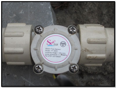
Water flow sensor consists of a plastic valve body, a water rotor, and a hall-effect sensor. When water flows through the rotor, rotor rolls. Its speed changes with different rate of flow. The hall-effect sensor outputs the corresponding pulse Signal. They use acoustic waves and electromagnetic fields to measure the flow through a given area via physical quantities, such as acceleration, frequency, pressure and volume. As a result, many flow meters are named with respect to the physical property that helps to measure the flow.
Figure1: water flow sensor
The flow rate as determined by the flow sensor is derived from other physical properties. The relationship between the physical properties and the flow rate is derived from fundamental fluid flow principles, such as Bernoulli’s equation.
Features:
Specifications:
Communication
The Arduino Uno has a number of facilities for communicating with a computer, another Arduino, or other microcontrollers. The ATmega328 provides UART TTL (5V) serial communication, which is available on digital pins 0 (RX) and 1 (TX). An ATmega16U2 on the board channels this serial communication over USB and appears as a virtual com port to software on the computer. The 16U2 firmware uses the standard USB COM drivers, and no external driver is needed. However, on Windows, a.inf file is required. The Arduino software includes a serial monitor which allows simple textual data to be sent to and from the Arduino board. The RX and TX LEDs on the board will flash when data is being transmitted via the USB-to-serial chip and USB connection to the computer. A Software Serial library allows for serial communication on any of the Uno's digital pins. The ATmega328 also supports I2C (TWI) and SPI communication. The Arduino software includes a Wire library to simplify use of the I2C bus. For SPI communication, use the SPI library.
ZIGBEE
Introduction
ZigBee is the only open, global wireless standard to provide the foundation for the Internet of Things by enabling simple and smart objects to work together, improving comfort and efficiency in everyday life.
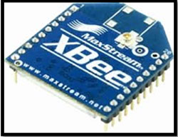
Figure2: ZigBee module
2.2.3 Overview
Zigbee is wireless technology defined by IEEE 802.15.4 Personal Area Network standard. It is primarily designed for the wide range controlling applications and to replace the existing non-standard technologies. It currently operates in 868 MHz band at a data rate of 20Kbps in Europe, 914MHz band at 40kbps in USA, and the 2.4GHz ISM bands Worldwide at a maximum data-rate of 250kbps. One of the main advantages of this ZIGBEE communication is that it provides a noise free communication, the amount of noise added in this type of communication is very less compared to the other wireless communications.
The Zigbee modules further divided into two categories. They are Zigbee (Xbee) and the other is Zigbee pro (Xbee Pro). The Pro series features improvements in both range and power management. Due to these features, these modules have been chosen for the wireless communication component in the system.
Description:
In a system of water carrying pipelines we insert number of water flow sensors along with Arduino and Zigbee at different places based on Zigbee distance. The water flow sensor assigned in line with the water carrying pipeline takes the reading of water flow and convert it to pulses which given to Arduino after processing the data given to Zigbee at End device. The coordinator Zigbee at a distance collect the information from different Zigbee’s placed at different sensor nodes, these data will be displayed Desktop PC at Coordinator Zigbee. The block diagrams wireless sensor node and Coordinator is shown Figure3 and Figure4.
The connections of water flow sensor and Zigbee to Arduino is simple. The water flow sensor has three wires the Red wires connected 5V of Arduino, Black wire is connected ground and yellow wire is signal connected to the interrupt signal of Arduino pin2. The Zigbee has three connections one is ground, TX and RX pins are connected to ground, RX and TX pins of Arduino respectively. The Circuit diagram image is shown in Figure5.
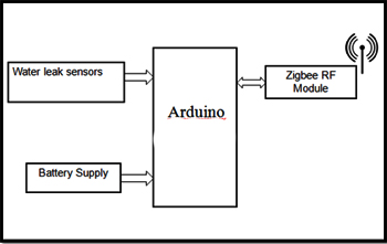
Figure3: Block diagram Wireless sensor node
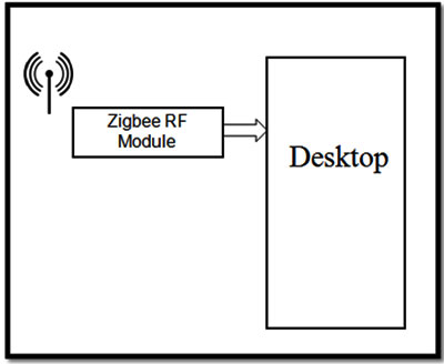
Figure4: Block diagram Coordinator
Program:
int pulse; //measuring the rising edges of the signal
int Calc;
int flowsensor = 2; //The pin location of the sensor
void rpm () //This is the function that the interrupt calls
{
pulse++; //This function measures the rising and falling edge of the hall effect
//sensors signal
}
// The setup() method runs once, when the program starts
void setup()
{
pinMode(flowsensor, INPUT); //initializes digital pin 2 as an input
Serial.begin(9600); //This is the setup function where the serial port is
//initialised,
attachInterrupt(0, rpm, RISING); //and the interrupt is attached
}
// the loop() method runs over and over again, as long as the Arduino has power
void loop ()
{
pulse = 0; //Set pulse to 0 ready for calculations
sei(); //Enables interrupts
delay (1000); //Wait 1 second
cli(); //Disable interrupts
//(Pulse frequency x 60) / 7.5Q, = flow rate
Calc = (pulse *60 /7.5);
Serial.print("flowrate at node1");
Serial.print (Calc, DEC); //Prints the number calculated above
Serial.print (" Ltr/min\r\n"); //Prints "L/min" and returns a new line
}
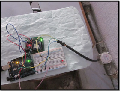
Figure5: Wireless Sensor node with Arduino, Zigbee and water flow sensor
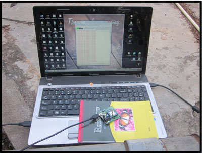
Figure6: Coordinator Zigbee connected laptop
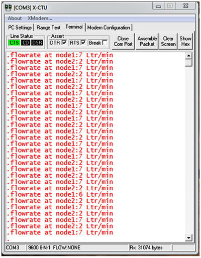
Figure7: Flow rate displayed on PC
In this Article we will learn how to interface water flow sensor and Zigbee to Arduino.
The Components required:
- Arduino uno board with cable,
- Zigbee modules,
- Water Flow meters,
- Bread board with jumpers
Software tools required:
- Arduino IDE
- X-CTU
Water Flow Sensors
Introduction:
Flow is defined as the rate (volume or area per unit time) at which a substance travels through a given cross section and is characterized at specific temperatures and pressures. The instruments used to measure flow are termed flow meters. The main components of a flow meter include the sensor, signal processor and transmitter
Water flow sensor:
Water flow sensor consists of a plastic valve body, a water rotor, and a hall-effect sensor. When water flows through the rotor, rotor rolls. Its speed changes with different rate of flow. The hall-effect sensor outputs the corresponding pulse Signal. They use acoustic waves and electromagnetic fields to measure the flow through a given area via physical quantities, such as acceleration, frequency, pressure and volume. As a result, many flow meters are named with respect to the physical property that helps to measure the flow.
Figure1: water flow sensor
The flow rate as determined by the flow sensor is derived from other physical properties. The relationship between the physical properties and the flow rate is derived from fundamental fluid flow principles, such as Bernoulli’s equation.
Features:
- Compact, Easy to Install
- High Sealing Performance
- High Quality Hall Effect Sensor
Specifications:
- Minimum Working Voltage: DC 4.5V
- Maximum Working Current: 15mA (DC 5V)
- Working Voltage: DC 5V~24V
- Flow Rate Range: 1~30L/min
- Load Capacity: = 10mA (DC 5V)
- Operating Temperature: = 80?
- Water Pressure: = 1.75MPa
- Storage Temperature: -25~+ 80?
Communication
The Arduino Uno has a number of facilities for communicating with a computer, another Arduino, or other microcontrollers. The ATmega328 provides UART TTL (5V) serial communication, which is available on digital pins 0 (RX) and 1 (TX). An ATmega16U2 on the board channels this serial communication over USB and appears as a virtual com port to software on the computer. The 16U2 firmware uses the standard USB COM drivers, and no external driver is needed. However, on Windows, a.inf file is required. The Arduino software includes a serial monitor which allows simple textual data to be sent to and from the Arduino board. The RX and TX LEDs on the board will flash when data is being transmitted via the USB-to-serial chip and USB connection to the computer. A Software Serial library allows for serial communication on any of the Uno's digital pins. The ATmega328 also supports I2C (TWI) and SPI communication. The Arduino software includes a Wire library to simplify use of the I2C bus. For SPI communication, use the SPI library.
ZIGBEE
Introduction
ZigBee is the only open, global wireless standard to provide the foundation for the Internet of Things by enabling simple and smart objects to work together, improving comfort and efficiency in everyday life.
Figure2: ZigBee module
2.2.3 Overview
Zigbee is wireless technology defined by IEEE 802.15.4 Personal Area Network standard. It is primarily designed for the wide range controlling applications and to replace the existing non-standard technologies. It currently operates in 868 MHz band at a data rate of 20Kbps in Europe, 914MHz band at 40kbps in USA, and the 2.4GHz ISM bands Worldwide at a maximum data-rate of 250kbps. One of the main advantages of this ZIGBEE communication is that it provides a noise free communication, the amount of noise added in this type of communication is very less compared to the other wireless communications.
The Zigbee modules further divided into two categories. They are Zigbee (Xbee) and the other is Zigbee pro (Xbee Pro). The Pro series features improvements in both range and power management. Due to these features, these modules have been chosen for the wireless communication component in the system.
Description:
In a system of water carrying pipelines we insert number of water flow sensors along with Arduino and Zigbee at different places based on Zigbee distance. The water flow sensor assigned in line with the water carrying pipeline takes the reading of water flow and convert it to pulses which given to Arduino after processing the data given to Zigbee at End device. The coordinator Zigbee at a distance collect the information from different Zigbee’s placed at different sensor nodes, these data will be displayed Desktop PC at Coordinator Zigbee. The block diagrams wireless sensor node and Coordinator is shown Figure3 and Figure4.
The connections of water flow sensor and Zigbee to Arduino is simple. The water flow sensor has three wires the Red wires connected 5V of Arduino, Black wire is connected ground and yellow wire is signal connected to the interrupt signal of Arduino pin2. The Zigbee has three connections one is ground, TX and RX pins are connected to ground, RX and TX pins of Arduino respectively. The Circuit diagram image is shown in Figure5.
Figure3: Block diagram Wireless sensor node
Figure4: Block diagram Coordinator
Program:
int pulse; //measuring the rising edges of the signal
int Calc;
int flowsensor = 2; //The pin location of the sensor
void rpm () //This is the function that the interrupt calls
{
pulse++; //This function measures the rising and falling edge of the hall effect
//sensors signal
}
// The setup() method runs once, when the program starts
void setup()
{
pinMode(flowsensor, INPUT); //initializes digital pin 2 as an input
Serial.begin(9600); //This is the setup function where the serial port is
//initialised,
attachInterrupt(0, rpm, RISING); //and the interrupt is attached
}
// the loop() method runs over and over again, as long as the Arduino has power
void loop ()
{
pulse = 0; //Set pulse to 0 ready for calculations
sei(); //Enables interrupts
delay (1000); //Wait 1 second
cli(); //Disable interrupts
//(Pulse frequency x 60) / 7.5Q, = flow rate
Calc = (pulse *60 /7.5);
Serial.print("flowrate at node1");
Serial.print (Calc, DEC); //Prints the number calculated above
Serial.print (" Ltr/min\r\n"); //Prints "L/min" and returns a new line
}
Figure5: Wireless Sensor node with Arduino, Zigbee and water flow sensor
Figure6: Coordinator Zigbee connected laptop
Figure7: Flow rate displayed on PC
Published date : 20 May 2015 02:41PM