

Sakshi Education
If you want to get the Information from Arduino, One of the easiest way to communicate is to attach a character LCD. These LCD modules are a lot of fun. In this Article we will study how to interface 16X2 LCD modules to Arduino and Display Characters on the LCD Display.
16×2 LCD module:
Introduction:
A liquid crystal display (LCD) is a thin, flat electronic visual display that uses the light modulating properties of liquid crystals (LCs). LCs does not emit light directly.
They are used in a wide range of applications, including computer monitors, television, instrument panels, aircraft cockpit displays, signage, etc. They are common in consumer devices such as video players, gaming devices, clocks, watches, calculators, and telephones. LCDs have replaced cathode ray tube (CRT) displays in most applications. They are usually more compact, lightweight, portable, less expensive, and more reliable. They are available in a wider range of screen sizes than CRT and plasma displays, since they do not use phosphors, they cannot suffer image burn-in. LCDs are more energy efficient and offer safer disposal than CRTs. Its low electrical power consumption enables it to be used in battery powered electronic equipment. It is an electronically modulated optical device made up of any number of pixels filled with liquid crystals and arrayed in front of a light source or reflector to produce images in color or mono chrome.
16×2 alphanumeric LCD modules are cheap and easy to interface to the Arduino Uno. They have 16 connections pins.
LCD Module Hardware:
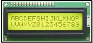
Figure1: 16X2 LCD module
The components required for this project are
The pin out of the module is:
Usually the device requires 8 data lines to provide data to Bits 0-7. However the device can be set to a “4 bit” mode which allows you to send data in two chunks or nibbles of 4 bits. This is great as it reduces the number of (Input/output) IO pin connections you require when interfacing with your Arduino.
Connections:
Table1: LCD connections with Arduino
NOTE:
In order to control the contrast we can adjust the voltage presented to Pin 3. This must be between 0 and 5V. We tied this pin to ground through potentiometer.
Pin 15 provides 5V to the backlight LED. It wasn’t clear on our device if this could be connected direct to 5V so we played safe and placed a 560ohm resistor in line with this pin.
Wiring Checks:
Here are some sanity checks before you power up your circuit for the first time:
Program:
#include
// Connections:
// rs (LCD pin 4) to Arduino pin 12
// rw (LCD pin 5) to Arduino pin 11
// enable (LCD pin 6) to Arduino pin 10
// LCD pin 15 to Arduino pin 13
// LCD pins d4, d5, d6, d7 to Arduino pins 5, 4, 3, 2
LiquidCrystal lcd(12, 11, 10, 5, 4, 3, 2);
int backLight = 13; // pin 13 will control the backlight
void setup()
{
pinMode(backLight, OUTPUT);
digitalWrite(backLight, HIGH); // turn backlight on. Replace 'HIGH' with 'LOW' to turn it off.
lcd.begin(16,2); // columns, rows. use 16,2 for a 16x2 LCD, etc.
lcd.clear(); // start with a blank screen
lcd.setCursor(0,0); // set cursor to column 0, row 0 (the first row)
lcd.print("hello, World!"); // change this text to whatever you like
}
void loop()
{
}
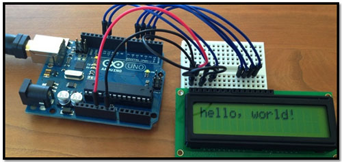
Figure2: LCD with Arduino
16×2 LCD module:
Introduction:
A liquid crystal display (LCD) is a thin, flat electronic visual display that uses the light modulating properties of liquid crystals (LCs). LCs does not emit light directly.
They are used in a wide range of applications, including computer monitors, television, instrument panels, aircraft cockpit displays, signage, etc. They are common in consumer devices such as video players, gaming devices, clocks, watches, calculators, and telephones. LCDs have replaced cathode ray tube (CRT) displays in most applications. They are usually more compact, lightweight, portable, less expensive, and more reliable. They are available in a wider range of screen sizes than CRT and plasma displays, since they do not use phosphors, they cannot suffer image burn-in. LCDs are more energy efficient and offer safer disposal than CRTs. Its low electrical power consumption enables it to be used in battery powered electronic equipment. It is an electronically modulated optical device made up of any number of pixels filled with liquid crystals and arrayed in front of a light source or reflector to produce images in color or mono chrome.
16×2 alphanumeric LCD modules are cheap and easy to interface to the Arduino Uno. They have 16 connections pins.
LCD Module Hardware:
Figure1: 16X2 LCD module
The components required for this project are
- Arduion Uno Board with USB cable
- Bread Board with jumpers cables
- 16X2 LCD module
- Potentiometer
- 560 ohm resistor
The pin out of the module is:
- Ground
- VCC (Usually +5V)
- Contrast adjustment (VO)
- Register Select (RS). RS=0: Command, RS=1: Data
- Read/Write (R/W). R/W=0: Write, R/W=1: Read
- Enable
- Bit 0 (Not required in 4-bit operation)
- Bit 1 (Not required in 4-bit operation)
- Bit 2 (Not required in 4-bit operation)
- Bit 3 (Not required in 4-bit operation)
- Bit 4
- Bit 5
- Bit 6
- Bit 7
- LED Backlight Anode (+)
- LED Backlight Cathode (-)
Usually the device requires 8 data lines to provide data to Bits 0-7. However the device can be set to a “4 bit” mode which allows you to send data in two chunks or nibbles of 4 bits. This is great as it reduces the number of (Input/output) IO pin connections you require when interfacing with your Arduino.
Connections:
| LCD Pin | Function | Arduino Uno board |
| 1 | GND(Vss) | GND pin |
| 2 | +5V (Vcc) | +5V pin |
| 3 | Contrast | Potentiometer to GND pin |
| 4 | RS | Pin12 |
| 5 | R/W | Pin11 |
| 6 | E | Pin10 |
| 7 | Data0 | No connection |
| 8 | Data1 | No connection |
| 9 | Data2 | No connection |
| 10 | Data3 | No connection |
| 11 | Data4 | Pin5 |
| 12 | Data5 | Pin4 |
| 13 | Data6 | Pin3 |
| 14 | Data7 | Pin2 |
| 15 | +5V via 560ohm | Resistor to pin13 |
| 16 | GND | GND pin |
Table1: LCD connections with Arduino
NOTE:
In order to control the contrast we can adjust the voltage presented to Pin 3. This must be between 0 and 5V. We tied this pin to ground through potentiometer.
Pin 15 provides 5V to the backlight LED. It wasn’t clear on our device if this could be connected direct to 5V so we played safe and placed a 560ohm resistor in line with this pin.
Wiring Checks:
Here are some sanity checks before you power up your circuit for the first time:
- Pin 2 should be tied to 5V. Pin 15 should have a resistor inline to 5V to protect the backlight.
- Pin 7-10 are unconnected.
- Pin 11-14 are connected to Arduino pins.
Program:
#include
// Connections:
// rs (LCD pin 4) to Arduino pin 12
// rw (LCD pin 5) to Arduino pin 11
// enable (LCD pin 6) to Arduino pin 10
// LCD pin 15 to Arduino pin 13
// LCD pins d4, d5, d6, d7 to Arduino pins 5, 4, 3, 2
LiquidCrystal lcd(12, 11, 10, 5, 4, 3, 2);
int backLight = 13; // pin 13 will control the backlight
void setup()
{
pinMode(backLight, OUTPUT);
digitalWrite(backLight, HIGH); // turn backlight on. Replace 'HIGH' with 'LOW' to turn it off.
lcd.begin(16,2); // columns, rows. use 16,2 for a 16x2 LCD, etc.
lcd.clear(); // start with a blank screen
lcd.setCursor(0,0); // set cursor to column 0, row 0 (the first row)
lcd.print("hello, World!"); // change this text to whatever you like
}
void loop()
{
}
Figure2: LCD with Arduino
Published date : 20 May 2015 02:19PM