

Sakshi Education

In this article we are going learn what is Zigbee technology and installation of X-CTU Software.
Description:
When you hold the TV remote and wish to use it you have to necessarily point your control at the device. This one-way, line-of-sight, short-range communication uses infrared (IR) sensors to enable communication and control and it is possible to operate the TV remotely only with its control unit. Now picture a home with entertainment units, security systems including fire alarm, smoke detector and burglar alarm, air-conditioners and kitchen appliances all within whispering distance from each other and imagine a single unit that talks with all the devices, no longer depending on line-of-sight, and traffic no longer being one-way. This means that the devices and the control unit would all need a common standard to enable intelligible communication. ZigBee is such a standard for embedded.
Zigbee is wireless technology defined by IEEE 802.15.4 Personal Area Network standard. It is primarily designed for the wide range controlling applications and to replace the existing non-standard technologies. It currently operates in 868 MHz band at a data rate of 20Kbps in Europe, 914MHz band at 40kbps in USA, and the 2.4GHz ISM bands Worldwide at a maximum data-rate of 250kbps. One of the main advantages of this ZIGBEE communication is that it provides a noise free communication, the amount of noise added in this type of communication is very less compared to the other wireless communications. The Zigbee modules further divided into two categories. They are Zigbee (Xbee) and the other is Zigbee pro (Xbee Pro). The Pro series features improvements in both range and power management. Due to these features, these modules have been chosen for the wireless communication component in the system.
Figure1: Zigbee
The components required are:
- Zigbee Series2 Coordinator Zigbee Series2 Router/End device.
- USB Interface Board (for interfacing between an RF module & host PC).
- RS-232 Interface Board (for looping data back to the base from a remote)
- PC (Windows 2000 or XP or 7) with an available USB (or RS-232) port.
Required installations
X-CTU Software & USB drivers
Installation of X-CTU software
X-CTU is a graphical Windows-based serial utility provided by Digi to program and configure the firmware on its RF products.
- Double-click “setup_X-CTU.exe” file and follow prompts of the installation screens. This file can be downloaded from the following website: https://digi-xctu.software.informer.com/download/
- Start X-CTU from the desktop icon.
PC Settings Tab
- Set the “PC Settings” tab to 9600 baud, hardware flow control, 8 data bits, parity NONE, 1 stop bit.
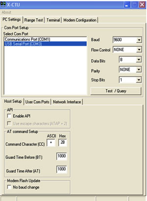
- Check “Enable API” under “Host Setup.” This box must be checked unless you reconfigure the Zigbee RF module with AT firmware.
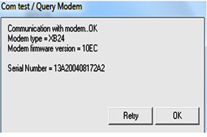
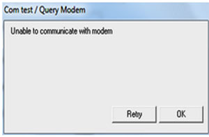
- Select the COM port the download cable is connected to, and then click Test/Query. A window should open to display the firmware version; otherwise a clear failure message is displayed. You may have to retry several times if your Zigbee RF module is currently configured as an end device and has the sleep mode enabled. Click OK in this window to close it.
Successful Test/Query
Failed Test/Query
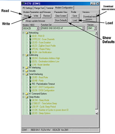
Modem Configuration Tab:
Profiles, firmware, and configurations for the Zigbee RF module are set using the “Modem Configuration” tab.
Load Existing Profile:
To get a default profile, click the Load button under “Profile” and browse the file from hard disk and open it using “read” button. After editing in that file we can write that on to firmware.
Install USB Drivers (Hardware USB Bus & Virtual COM Port drivers):
The following steps were recorded while using the Windows XP operating system.
- Verify the software cd is inserted into the CD drive.
- Connect the USB development board to a PC using USB cable.
After the module assembly is detected by the PC, a “Found New Hardware Wizard” dialog box should appear.
- Select the 'No, not this time' option; then select the 'Next' button.
- Select 'Install from a specific list or location (Advanced)' option; then select the 'Next' button.
- Select the 'Continue Anyway' button.
- Select the 'Finish' button.
- Repeat steps 2 through 6 to install the next driver.
- Reboot the PC if prompted to do so.
Discovery of all Nodes in a Network:
- Mount Zigbee Series2 Modules to the USB & RS-232 development boards.
- The module mounted to the USB board should be the Coordinator.
- The modules mounted to the RS-232 boards are all Router/End devices.
- After installing the X-CTU Software and USB drivers, connect the Coordinator module assembly to the PC using a standard USB cable. Connect power supplies and power on all other radios.
- Under the “PC Settings” tab select the COM port to which your Coordinator is attached.
- In the “Terminal” tab, enter command mode by observing the 1 second guard times before and after entering the “+++” command mode sequence. You should receive the “OK” response if command mode has been correctly entered.
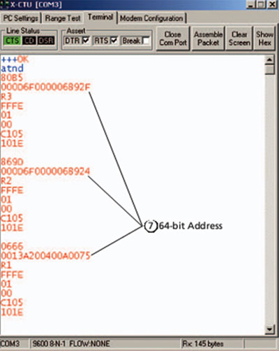
- From X-CTU, while in command mode (command mode will automatically be exited with 10 seconds of inactivity) enter the ATND command followed by a carriage return. All powered Router/End devices that have joined the network, will respond with their device information.
- The second field returned from the ATND parameter is the 64-bit address of each particular Router/End device.
Range Test:
Use the “Terminal” and “Range Test” tabs of the X-CTU Software to:
- Set parameters on the Coordinator module to communicate with a specific Router/End device module
- Determine the range capabilities of the Zigbee Series 2 Modules.
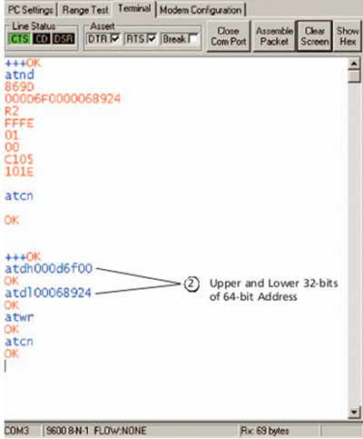
- Use the ATDH and ATDL commands to set the destination address high and the destination address low of the Coordinator to match the 64-bit address of the particular Router/End device with which you wish to communicate. Use ATDH for the upper 32 bits and ATDL for the lower 32 bits of the 64-bit address as shown in below figure. The “Modem Configuration” tab can be used to do this as well.
- The Serial Loopback Adaptor should be placed on the Router/End device whose 64-bit address has been entered with the ATDH and ATDL parameters from the Coordinator.
- Select the “Range Test” tab.
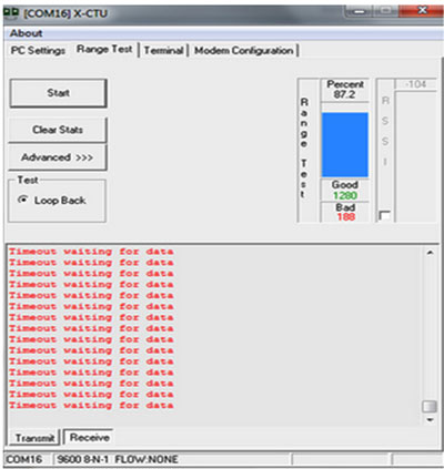
- Click the 'Start' button to begin the range test.
- Move the Router/End device (with red Serial Loopback Adaptor) away from the Coordinator to find the maximum range of the wireless link.
- Change the Loopback Adaptor to any other Router/End device and repeat if desired.
- Mesh networking capabilities can be observed by moving the Router/End device that you are communicating with out of range of the Coordinator. Power another Router/End device between the Coordinator and the out of range Router/End device to re-establish communications. Messages are now being routed through the new Router/End device.
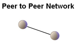
ZigBee networks can be configured to operate in a variety of different ways to suit the application and environment. One of the topology is Peer to Peer topology.
Peer to Peer topology: In this the Zigbee nodes connect directly to each other for peer to peer communication. Here the information is transmitted from one source point other source point and vice versa.
Internal Architecture of Zigbee:
Looking at the Zigbee pin out we can see right away the different types of input that can be translated and transmitted wirelessly:
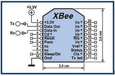
Figure3: Internal structure of Zigbee
- Digital I/O
- Analog I/O (10 bit resolution)
- Pulse with Modulation
- Serial Communication (SPI/RS232/I2C )
- CTS/DTR Control Signals
These are some the most common types of signals that are used in basic electronics equipments and the Zigbee offer them all as inputs and outputs. The Zigbee is configured for 9600bps serial communication.
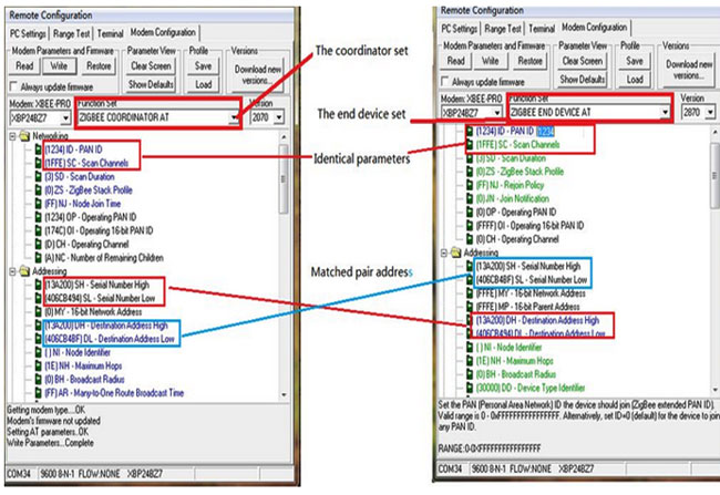
Figure4: pairing two devices as Coordinator and End device
Published date : 16 May 2015 02:11PM