

Sakshi Education
In this Article we will study how to interact with external world using Arduino Uno GPIO’s. In this tutorial we are going to see how to use an Arduino to control input and output from external sources. Here we are going to see two simple projects.
The learning from this project is how to interface a LED to the Arduino.
Let us start with simple led project, which consists of an external led connected to Arduino where a led is turned on and off continuously based on some delay. As we know that the Arduino Uno has 14 digital pins, we will write a program in order to make the external LED On and Off continuously by using the pins of the microcontroller. This external LED is connected to the 12th pin of Arduino Uno through a resistor of value 330 ohms.
The components required for this project are:
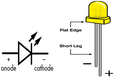
Figure1: LED Symbol with polarity
The Figure1 shows the LED symbol and polarity indications. The polarity of LED indicates that the positive side of led is called ‘anode’ and is marked by having a longer leg. The other side indicated that the negative side of led is called ‘cathode’ is marked by having shorter leg as shown in the figure.
Setting up circuit:
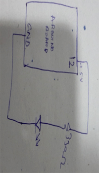
Figure2: Circuit Diagram
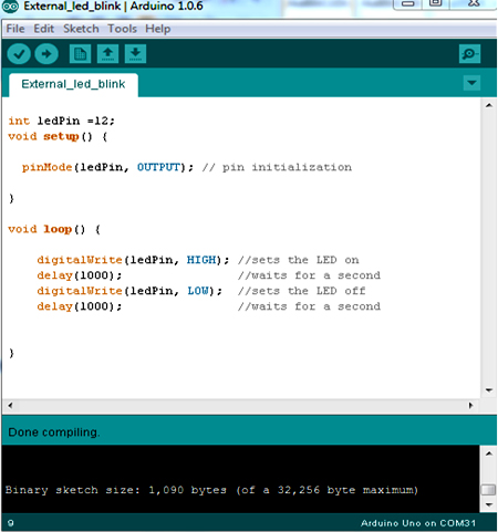
The program for LED blinks:
Program:
int ledPin = 12;
void setup()
{
pinMode(ledPin, OUTPUT); //initialization of ledpin as output
}
void loop() // run over and over again
{
digitalWrite(ledPin, HIGH); // sets the LED on
delay(1000); // waits for a second
digitalWrite(ledPin, LOW); // sets the LED off
delay(1000); // waits for a second
}
Program Explanation:
The following figure shows the external LED is connected to Arduino board which is blinking the continuously for one second of delay.
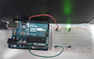
Figure3: External Led connected to Arduino board
2. Switch on a LED when switch is closed
The learning from this project is how to interface a push button to the Arduino.
In this project we are going to learn, how to use Arduino GPIO’s as inputs and outputs that is based on the input value the output will be varying. A switch (push button) is connected to the Arduino as an input pin and Led is connected to Arduino as an output pin, when the switch is closed (pressed), the LED switches on, when the switch is opened (released), and the LED switches off.
Switch (Pushbutton)
The push button connects two points in a circuit when you press it. The push button sits between a pull-up resistor and ground. When the push button is open (unpressed) there is no connection between two legs of push button, so the pin is connected to ground through pull down resistor and we read a low output signal from push button. When the push button is closed (pressed) then it makes connection between two legs of the push button and connecting the pin to 5V and we read a high output signal from push button.
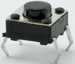
Figure4: Pushbutton
The components required for this project are,
Arduion Uno Board with USB cable
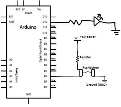
Figure5: Circuit diagram
Program:
int buttonpin = 2;
int ledpin = 12;
void setup() {
pinMode(buttonpin, INPUT);
pinMode(ledpin, OUTPUT);
}
void loop() {
int buttonstate;
buttonstate = digitalRead(buttonpin);
if (buttonstate == LOW )
{
digitalWrite(ledpin, HIGH);
}
else
{
digitalWrite(ledpin, LOW);
}
}
Program Explanation:
- Blinking LED using an Arduino
- Switch on a LED when switch is closed(Push button)
The learning from this project is how to interface a LED to the Arduino.
Let us start with simple led project, which consists of an external led connected to Arduino where a led is turned on and off continuously based on some delay. As we know that the Arduino Uno has 14 digital pins, we will write a program in order to make the external LED On and Off continuously by using the pins of the microcontroller. This external LED is connected to the 12th pin of Arduino Uno through a resistor of value 330 ohms.
The components required for this project are:
- Arduion Uno Board with USB cable
- Breadboard with jumpers wires
- LED
- 330 ohm resistor
Figure1: LED Symbol with polarity
The Figure1 shows the LED symbol and polarity indications. The polarity of LED indicates that the positive side of led is called ‘anode’ and is marked by having a longer leg. The other side indicated that the negative side of led is called ‘cathode’ is marked by having shorter leg as shown in the figure.
Setting up circuit:
- Connect ground pin (GND) from the Arduino board to the bottom row of the breadboard with a jumper wire.
- Connect 5V pin from the Arduino board to the above the bottom row of the bread- board with a jumper wire.
- Connect the pin12th from Arduino board to long leg of the led via breadboard.
- Connect the short leg of the led to one end of resistor via breadboard.
- Connect the other end of resistor to the ground column of breadboard.
Figure2: Circuit Diagram
The program for LED blinks:
Program:
int ledPin = 12;
void setup()
{
pinMode(ledPin, OUTPUT); //initialization of ledpin as output
}
void loop() // run over and over again
{
digitalWrite(ledPin, HIGH); // sets the LED on
delay(1000); // waits for a second
digitalWrite(ledPin, LOW); // sets the LED off
delay(1000); // waits for a second
}
Program Explanation:
- int ledPin = 12
Here we are defining a variable by name “ledPin” which is assigned a pin number 12. So use of this variable anywhere in the program will mean use of the 12th pin for operations.
- Void setup ()
This part of the program consists of the code which is executed only once for pin initialization, etc.
- pinMode(ledPin , OUTPUT)
Syntax: pinMode (pin number / variable name, INPUT/OUTPUT);
pinMode is a keyword which initializes a pin which is specified by the pin number inside the parentheses and followed by the behavior of that pin i.e., whether that pin is acting as an Input or an Output Pin. Here in this code “ledPin” indicates pin number 12 which is to be initialized and that pin is acting as an Output pin.
- Void loop ()
This part of the code is to be repeated continuously until the Arduino Uno board power’s off.
- digitalWrite(ledpin , HIGH)
Syntax: digitalWrite (pin number / variable name, LOW / HIGH);
This line is used to write / send a digital signal value i.e., either low or high signal to the pin specified by the pin number. So ledPin indicates Pin number 12 to which a high signal is sent and in the next line a low signal is sent to pin number 12 after some delay.
- delay (1000)
Syntax: delay (time in milliseconds);
This statement helps us to put delays/ time gaps in milliseconds (ms). So here delay (1000) gives a delay of 1000 ms which is equal to 1 second.
The following program compiled and flashed into the Arduino board.
The following figure shows the external LED is connected to Arduino board which is blinking the continuously for one second of delay.
Figure3: External Led connected to Arduino board
2. Switch on a LED when switch is closed
The learning from this project is how to interface a push button to the Arduino.
In this project we are going to learn, how to use Arduino GPIO’s as inputs and outputs that is based on the input value the output will be varying. A switch (push button) is connected to the Arduino as an input pin and Led is connected to Arduino as an output pin, when the switch is closed (pressed), the LED switches on, when the switch is opened (released), and the LED switches off.
Switch (Pushbutton)
The push button connects two points in a circuit when you press it. The push button sits between a pull-up resistor and ground. When the push button is open (unpressed) there is no connection between two legs of push button, so the pin is connected to ground through pull down resistor and we read a low output signal from push button. When the push button is closed (pressed) then it makes connection between two legs of the push button and connecting the pin to 5V and we read a high output signal from push button.
Figure4: Pushbutton
The components required for this project are,
Arduion Uno Board with USB cable
- Bread Board with jumpers wires
- Push button
- LED
- 330 ohms and 10k ohms resistors
- Connect ground pin (GND) from the Arduino board to the bottom row of the bread board with a jumper wire.
- Connect 5V pin from the Arduino board to the above the bottom row of the bread board with a jumper wire.
- Connect two long vertical rows of pushbutton on the side of breadboard to provide access to the 5 volts and to the ground.
- Connect pin2 to the one leg of the pushbutton and same leg of pushbutton connected to 5 volts through a pull down resistor (10K Ohms).
- Connect the other leg of pushbutton to ground via breadboard.
- Connect the pin12th from Arduino board to long leg of the led via breadboard.
- Connect the short leg of the led to one end of resistor via breadboard.
- Connect the other end of resistor to the ground column of breadboard.
Figure5: Circuit diagram
Program:
int buttonpin = 2;
int ledpin = 12;
void setup() {
pinMode(buttonpin, INPUT);
pinMode(ledpin, OUTPUT);
}
void loop() {
int buttonstate;
buttonstate = digitalRead(buttonpin);
if (buttonstate == LOW )
{
digitalWrite(ledpin, HIGH);
}
else
{
digitalWrite(ledpin, LOW);
}
}
Program Explanation:
- int buttonpin = 2;
int ledpin = 12 ;
Here we are defining the variables by names “buttonpin” which is assigned to pin number 2 and “ledpin” which is assigned a pin number 12.
- Void setup()
This part of the program consists of the code which is executed only once when the program starts.
- pinMode(buttonpin , INPUT) :
pinMode(ledpin , OUTPUT);
Syntax: pinMode (pin number / variable name, INPUT/OUTPUT) ;
pinMode is a keyword which initializes a pin which is specified by the pin number inside the parentheses and followed by the behavior of that pin i.e., whether that pin is acting as an Input or an Output Pin. Here in this code “buttonpin” as input pin and “ledpin” as output pin.
- Void loop (): This part of the code is to be repeated continuously until Arduino board powers off.
- int buttonstate; here buttonstate variable is defined.
buttonState = digitalRead(buttonInput);
Reads or checks the value for whether the button is pressed (HIGH) or not (LOW).
- if – else :
Here we make use of if-else statement. That means if the button is pressed then LEDs will glow else they remain off.
- digitalWrite (ledpin , HIGH/LOW) :
Syntax: digitalWrite (pin number / variable name, HIGH/LOW);
This line is used to write / send a digital signal value i.e., either low or high signal to the pin specified by the pin number. So ledPin indicates Pin number 12 to which a high/low signal is sent.
The below figure shows that the external led’s connected to the Arduino board are OFF when the Switch is not pressed and the LEDs on breadboard will glow when the switch is pressed.
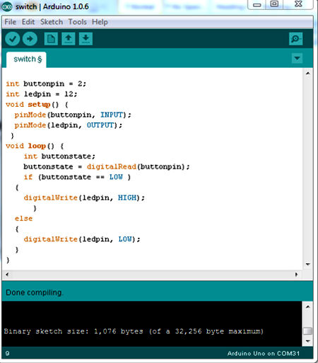
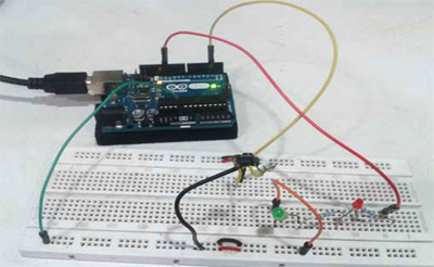
Figure6: led are off when the pushbutton is not pressed
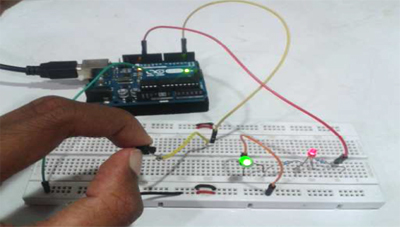
Figure7: led are on when the pushbutton is not pressed
Published date : 07 Mar 2015 04:59PM