

Sakshi Education
In this Article we will study how to move things with microcontrollers, In that case there are three types of motors are most commonly used: DC motors, Servomotors, and Stepper motors. Motors convert electrical energy into mechanical energy so that you can move things in the physical world. They are based on the electrical principle of induction. When you put electric current through a wire, it generates a magnetic field around the wire.
Motor Characteristics:
There are some common characteristics to all types of motors, they are as follows.
The learning from this project is how to interface DC motor to the Arduino and move the things with the Arduino board.
The components required for this project are
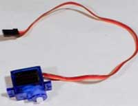
Figure6: Servo motor
Hardware connections:
The servo has a cable attached to it with three wires. Because the cable ends in a socket, you can use jumper wires to connect between the Arduino and the servo. Just plug the jumper wires directly into the socket. Connect the Red wire to 5 Volts Connect the yellow wire to digital pin 9 Connect the Brown wire to ground. Note that servos can use a lot of power, which can cause your Arduino to reset or behave differently. If you're using large servos then it is better to provide them with separate 5V supply for servos.
Program:
#include
Servo servo1; // servo control object
void setup() {
servo1.attach(9); //"attach" the servo1 object to digital pin 9
}
void loop() {
int position; // servo cannot turn a full of 360 degrees but it
// turn in between 0 to 180 degrees
servo1.write(90); // Tell servo to go to 90 degrees
delay(1000); // Pause to get it time to move
servo1.write(180); // Tell servo to go to 180 degrees
delay(1000); // Pause to get it time to move
servo1.write(0); // Tell servo to go to 0 degrees
delay(1000); // Pause to get it time to move
// Tell servo to go to 180 degrees, stepping by two degrees
for(position = 0; position < 180; position += 2)
{
servo1.write(position);
delay(20);
}
// Tell servo to go to 0 degrees, stepping by one degree
for(position = 180; position >= 0; position -= 1)
{
servo1.write(position);
delay(20);
}
}
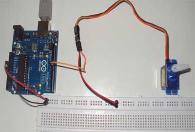
Figure6: Servo motor running with Arduino
Motor Characteristics:
There are some common characteristics to all types of motors, they are as follows.
- Voltage
The rated voltage of a motor is the voltage at which the motor operates at peak efficiency. Most DC motors can be operated somewhat above or below their range, but it is better to operate at their rated voltage. Dropping below rated voltage reduces the motor’s power, and operating above the rated voltage may spoil the motor.
- Current
Motors draw current depending on the load they are pulling. Usually more load means more current. Every motor has a stall current, which is the current it draws when it is stopped by an opposing force. This stall current is much greater than the running current, or current that it draws under no load. Your power supply for a motor should be able to handle the stall current with extra amperes to spare. Motors may draw near the stall current for a brief period of time when starting up, to overcome their inertia.
- Speed
Motor speed is given in revolutions per minute (RPMs).
- Torque
Torque is the measure of a motors pulling force. It is measured by the force a motor can pull when the opposing force is attached to a shaft attached to its center rod.
- Resistance
Resistance gives you the motors coil offers. By using Ohms Law, you can calculate the motors current draw if you know the rated voltage and the coil resistance.
- Driving a DC motor
- Driving a Servo motor
The learning from this project is how to interface DC motor to the Arduino and move the things with the Arduino board.
The components required for this project are
- Arduion Uno Board with USB cable
- Bread Board with jumpers cables
- DC motor
- L293D IC
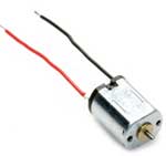
The DC Motor is the simplest of all the motors. There are two terminals, and when you apply direct current to one terminal and ground the other, the motor spins in one direction. When you apply current to the other terminal and ground the first terminal, the motor spins in the opposite direction. By switching the polarity of the terminals, you reverse the direction of the motor. By varying the current supplied to the motor, you vary the speed of the motor. DC motors are usually very fast, often spinning at several thousand revolutions per minute.
Figure1: DC motor
DC Motor Control
There are two controllable parameters of a DC motor, direction and speed. To control the direction, you reverse the direction of the voltage through the motor. To control the speed, use the pulse width modulation (PWM).
Direction
To control a DC motor from a microcontroller, you use switching arrangement known as an H-Bridge, consisting of four switches with the motor in the center. The schematic for an H-Bridge is shown in the following figure2. When the switches 1 and 4 are closed and 2 and 3 are open, voltage flows from the supply to 1 to the motor to 4 to ground. When 2 and 3 are closed and 1 and 4 are open, polarity is reversed, and voltage flows from the supply to 3 to the motor to 2 to ground.
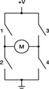
Figure2: H-Bridge
Speed
DC motor speed is proportional to the supplied voltage. If the voltage drops too far, the motor does not get enough power to turn, but within a certain range, usually 50% of the rated voltage, the motor will run at varying speeds. The most effective way to adjust the speed is by using pulse width modulation.
Hardware Connectons:
Interface DC Motors to Arduino using l293d IC. L293D is an IC which acts as a regulator thereby balancing and stabilizing the fluctuations received. L293D has 16 pins of which 2 pins are used as inputs to DC motor, two will be the outputs an enable pin a power source and a power supply with a battery. The 5V Vcc supply is used to power the Arduino board. The IC has two grounds (GND) to connect each DC motor. L293D IC contains two in-built H-bridge driver circuits. The two DC motors can be driven simultaneously, both in forward and reverse direction. The motor operations of two motors can be controlled by input logic at pins 2 and 7 and 10 and 15. Input logic 00 or 11 will stop the corresponding motor. Logic 01 and 10 will rotate it in clockwise and anticlockwise directions, respectively.
Enable pins 1 and 9 must be high for motors to start operating. When an enable input is high, the associated driver gets enabled. As a result, the outputs become active and work in phase with their inputs. Similarly, when the enable input is low, that driver is disabled, and their outputs are off and in the high-impedance state.
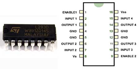
Figure3: L239D IC and Pinout Diagrams
Program:
#define E1 10 // Enable Pin for motor 1
#define E2 11 // Enable Pin for motor 2
#define I1 8 // Control pin 1 for motor 1
#define I2 9 // Control pin 2 for motor 1
#define I3 12 // Control pin 1 for motor 2
#define I4 13 // Control pin 2 for motor 2
void setup()
{
pinMode(E1, OUTPUT);
pinMode(E2, OUTPUT);
pinMode(I1, OUTPUT);
pinMode(I2, OUTPUT);
pinMode(I3, OUTPUT);
pinMode(I4, OUTPUT);
}
void loop()
{
digitalWrite(E1, HIGH);
digitalWrite(E2, HIGH);
digitalWrite(I1, HIGH);
digitalWrite(I2, LOW);
digitalWrite(I3, HIGH);
digitalWrite(I4, LOW);
delay(10000);
// change direction
digitalWrite(E1, LOW);
digitalWrite(E2, LOW);
delay(200);
digitalWrite(E1, HIGH);
digitalWrite(E2, HIGH);
digitalWrite(I1, LOW);
digitalWrite(I2, HIGH);
digitalWrite(I3, LOW);
digitalWrite(I4, HIGH);
delay(10000);
}
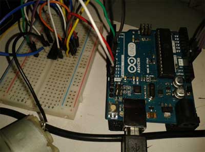
Figure4: Circuit Connections
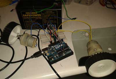
Figure5: Two DC motors connected with Arduino
2.Driving a Servo motor using an Arduino
The learning from this project is how to interface Servo motor to the Arduino and move the things with the Arduino.
The components required for this project are
Figure1: DC motor
DC Motor Control
There are two controllable parameters of a DC motor, direction and speed. To control the direction, you reverse the direction of the voltage through the motor. To control the speed, use the pulse width modulation (PWM).
Direction
To control a DC motor from a microcontroller, you use switching arrangement known as an H-Bridge, consisting of four switches with the motor in the center. The schematic for an H-Bridge is shown in the following figure2. When the switches 1 and 4 are closed and 2 and 3 are open, voltage flows from the supply to 1 to the motor to 4 to ground. When 2 and 3 are closed and 1 and 4 are open, polarity is reversed, and voltage flows from the supply to 3 to the motor to 2 to ground.
Figure2: H-Bridge
Speed
DC motor speed is proportional to the supplied voltage. If the voltage drops too far, the motor does not get enough power to turn, but within a certain range, usually 50% of the rated voltage, the motor will run at varying speeds. The most effective way to adjust the speed is by using pulse width modulation.
Hardware Connectons:
Interface DC Motors to Arduino using l293d IC. L293D is an IC which acts as a regulator thereby balancing and stabilizing the fluctuations received. L293D has 16 pins of which 2 pins are used as inputs to DC motor, two will be the outputs an enable pin a power source and a power supply with a battery. The 5V Vcc supply is used to power the Arduino board. The IC has two grounds (GND) to connect each DC motor. L293D IC contains two in-built H-bridge driver circuits. The two DC motors can be driven simultaneously, both in forward and reverse direction. The motor operations of two motors can be controlled by input logic at pins 2 and 7 and 10 and 15. Input logic 00 or 11 will stop the corresponding motor. Logic 01 and 10 will rotate it in clockwise and anticlockwise directions, respectively.
Enable pins 1 and 9 must be high for motors to start operating. When an enable input is high, the associated driver gets enabled. As a result, the outputs become active and work in phase with their inputs. Similarly, when the enable input is low, that driver is disabled, and their outputs are off and in the high-impedance state.
Figure3: L239D IC and Pinout Diagrams
Program:
#define E1 10 // Enable Pin for motor 1
#define E2 11 // Enable Pin for motor 2
#define I1 8 // Control pin 1 for motor 1
#define I2 9 // Control pin 2 for motor 1
#define I3 12 // Control pin 1 for motor 2
#define I4 13 // Control pin 2 for motor 2
void setup()
{
pinMode(E1, OUTPUT);
pinMode(E2, OUTPUT);
pinMode(I1, OUTPUT);
pinMode(I2, OUTPUT);
pinMode(I3, OUTPUT);
pinMode(I4, OUTPUT);
}
void loop()
{
digitalWrite(E1, HIGH);
digitalWrite(E2, HIGH);
digitalWrite(I1, HIGH);
digitalWrite(I2, LOW);
digitalWrite(I3, HIGH);
digitalWrite(I4, LOW);
delay(10000);
// change direction
digitalWrite(E1, LOW);
digitalWrite(E2, LOW);
delay(200);
digitalWrite(E1, HIGH);
digitalWrite(E2, HIGH);
digitalWrite(I1, LOW);
digitalWrite(I2, HIGH);
digitalWrite(I3, LOW);
digitalWrite(I4, HIGH);
delay(10000);
}
Figure4: Circuit Connections
Figure5: Two DC motors connected with Arduino
2.Driving a Servo motor using an Arduino
The learning from this project is how to interface Servo motor to the Arduino and move the things with the Arduino.
The components required for this project are
- Arduion Uno Board with USB cable
- Bread Board with jumpers cables
- Servo motor
Figure6: Servo motor
Hardware connections:
The servo has a cable attached to it with three wires. Because the cable ends in a socket, you can use jumper wires to connect between the Arduino and the servo. Just plug the jumper wires directly into the socket. Connect the Red wire to 5 Volts Connect the yellow wire to digital pin 9 Connect the Brown wire to ground. Note that servos can use a lot of power, which can cause your Arduino to reset or behave differently. If you're using large servos then it is better to provide them with separate 5V supply for servos.
Program:
#include
Servo servo1; // servo control object
void setup() {
servo1.attach(9); //"attach" the servo1 object to digital pin 9
}
void loop() {
int position; // servo cannot turn a full of 360 degrees but it
// turn in between 0 to 180 degrees
servo1.write(90); // Tell servo to go to 90 degrees
delay(1000); // Pause to get it time to move
servo1.write(180); // Tell servo to go to 180 degrees
delay(1000); // Pause to get it time to move
servo1.write(0); // Tell servo to go to 0 degrees
delay(1000); // Pause to get it time to move
// Tell servo to go to 180 degrees, stepping by two degrees
for(position = 0; position < 180; position += 2)
{
servo1.write(position);
delay(20);
}
// Tell servo to go to 0 degrees, stepping by one degree
for(position = 180; position >= 0; position -= 1)
{
servo1.write(position);
delay(20);
}
}
Figure6: Servo motor running with Arduino
Published date : 14 May 2015 04:25PM