

Sakshi Education

Introduction:
Arduino is a single board microcontroller that can be of handy to develop multidisciplinary projects and it is an open-source electronics prototyping platform based on flexiblity, easy-to-use hardware and software. Arduino is a small computer that can be programmed with your instructions to interact with various forms of input and output devices. Arduino board allows you to create devices that can interact with world around you; it can sense the environment by receiving input from a variety of sensors and can affect its surroundings by controlling lights, motors, and other actuators. The microcontroller on the board is programmed using the Arduino programming language and the Arduino development environment.
Hardware:
The hardware consists of an 8-bit Atmel AVR microcontroller or a 32-bit atmel ARM with complementary components to facilitate programming and incorporate into other circuits. An important aspect of the Arduino is the standard way that connectors are exposed, allowing the CPU board to be connected to a variety of interchangeable add-on modules known as shields. Some shields communicate with the Arduino board directly over various pins, but many shields are individually addressable via an I²C serial bus, allowing many shields to be stacked and used in parallel. Official Arduino’s have used the mega AVR series of chips, specifically the ATmega8, ATmega168, ATmega328, ATmega1280, and ATmega2560. A handful of other processors have been used by Arduino compatibles.
Most of boards include a 5 volt linear regulator and a 16 MHz crystal oscillator (or ceramic resonator in some variants), although some designs such as the LilyPad run at 8 MHz and dispense with the on board voltage regulator due to specific form-factor restrictions.
An Arduino microcontroller is also pre-programmed with a boot loader that simplifies uploading of programs to the on-chip flash memory, compared with other devices that typically need an external programmer. At a conceptual level, when using the Arduino software stack, all boards are programmed over RS-232 serial connection, but the way this is implemented varies by hardware version. Serial Arduino boards contain a simple inveter circuit to convert between RS-232-level and TTL-level signals. Current Arduino boards are programmed via USB, implemented using USB-to-serial adapter chips such as the FTDI FT232. Some variants, such as the Arduino Mini and the unofficial Board uno, use a detachable USB-to-serial adapter board or cable, Bluetooth or other methods. (When used with traditional microcontroller tools instead of the Arduino IDE, standard AVR ISP programming is used.)
Software:
The Arduino IDE is a cross-platform application written in Java, and is derived from the IDE for the Processing programming language and Wiring project. It is designed to introduce programming to artists and other newcomers unfamiliar with software development. It includes a code editor with features such as syntax highlighting, brace matching, and automatic indentation, and is also capable of compiling and uploading programs to the board with a single click. There is typically no need to edit makefiles or run programs on a command-line interface. The Arduino IDE comes with a C/C++ library called "Wiring", which makes many common input/output operations much easier. Arduino programs are written in C/C++, although users only need to define two functions to make a run-able program:
It is a feature of most Arduino boards that they have an LED and load resistor connected between pin 13 and ground, a convenient feature for many simple tests. The Arduino IDE uses the GNU tool chain and AVR libc to compile programs, and uses avr dude to upload programs to the board. As the Arduino platform uses Atmel microcontroller development environment, AVR Studio or the newer Atmel Studio, may also be used to develop software for the Arduino.
The Arduino boards can be built by hand or purchased. The Arduino hardware reference designs (CAD files) are distributed under a Creative Commons Attribution Share-Alike 2.5 license and are available on the Arduino Web site. Layout and production files for some versions of the Arduino hardware are also available. The software can be downloaded for free and the source code for the IDE and the on-board library are available and released under the GPLv2 license. In our case we are using Arduino Uno board.
Arduino Uno:
The Arduino Uno is a microcontroller board based on the ATmega328. It has 14 digital input/output pins (of which 6 can be used as PWM outputs), 6 analog inputs, a 16 MHz ceramic resonator, a USB connection, a power jack, an ICSP header, and a reset button. It contains everything needed to support the microcontroller; simply connect it to a computer with a USB cable or power it with AC-to-DC adapter or battery to get started. The Uno differs from all preceding boards and it does not use the FTDI USB-to-serial driver chip. Instead, it features the Atmega16U2 (Atmega8U2 up to version R2) programmed as a USB-to-serial converter. Revision 2 of the Uno board has a resistor pulling the 8U2 HWB line to ground, making it easier to put into DFU mode. Revision 3 of the board has the following new features:
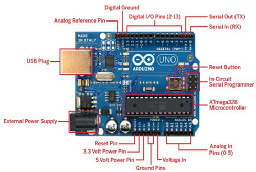
Figure1. Arduino Uno
Pin Description:
Power:
The Arduino Uno can be powered via the USB connection or with an external power supply. The power source is selected automatically. External power can come either from an AC-to-DC adapter or battery. The adapter can be connected by plugging a 2.1mm center-positive plug into the board's power jack. Leads from the battery can be inserted in the GND and VIN pin headers of the power connector. The board can operate on an external supply of 6 to 20 volts. If supplied with less than 7V, however, the 5V pin may supply less than five volts and the board may be unstable. If using more than 12V, the voltage regulator may overheat and damage the board. The recommended range is 7 to 12 volts.
The power pins are as follows:
Arduino is a single board microcontroller that can be of handy to develop multidisciplinary projects and it is an open-source electronics prototyping platform based on flexiblity, easy-to-use hardware and software. Arduino is a small computer that can be programmed with your instructions to interact with various forms of input and output devices. Arduino board allows you to create devices that can interact with world around you; it can sense the environment by receiving input from a variety of sensors and can affect its surroundings by controlling lights, motors, and other actuators. The microcontroller on the board is programmed using the Arduino programming language and the Arduino development environment.
Hardware:
The hardware consists of an 8-bit Atmel AVR microcontroller or a 32-bit atmel ARM with complementary components to facilitate programming and incorporate into other circuits. An important aspect of the Arduino is the standard way that connectors are exposed, allowing the CPU board to be connected to a variety of interchangeable add-on modules known as shields. Some shields communicate with the Arduino board directly over various pins, but many shields are individually addressable via an I²C serial bus, allowing many shields to be stacked and used in parallel. Official Arduino’s have used the mega AVR series of chips, specifically the ATmega8, ATmega168, ATmega328, ATmega1280, and ATmega2560. A handful of other processors have been used by Arduino compatibles.
Most of boards include a 5 volt linear regulator and a 16 MHz crystal oscillator (or ceramic resonator in some variants), although some designs such as the LilyPad run at 8 MHz and dispense with the on board voltage regulator due to specific form-factor restrictions.
An Arduino microcontroller is also pre-programmed with a boot loader that simplifies uploading of programs to the on-chip flash memory, compared with other devices that typically need an external programmer. At a conceptual level, when using the Arduino software stack, all boards are programmed over RS-232 serial connection, but the way this is implemented varies by hardware version. Serial Arduino boards contain a simple inveter circuit to convert between RS-232-level and TTL-level signals. Current Arduino boards are programmed via USB, implemented using USB-to-serial adapter chips such as the FTDI FT232. Some variants, such as the Arduino Mini and the unofficial Board uno, use a detachable USB-to-serial adapter board or cable, Bluetooth or other methods. (When used with traditional microcontroller tools instead of the Arduino IDE, standard AVR ISP programming is used.)
Software:
The Arduino IDE is a cross-platform application written in Java, and is derived from the IDE for the Processing programming language and Wiring project. It is designed to introduce programming to artists and other newcomers unfamiliar with software development. It includes a code editor with features such as syntax highlighting, brace matching, and automatic indentation, and is also capable of compiling and uploading programs to the board with a single click. There is typically no need to edit makefiles or run programs on a command-line interface. The Arduino IDE comes with a C/C++ library called "Wiring", which makes many common input/output operations much easier. Arduino programs are written in C/C++, although users only need to define two functions to make a run-able program:
- setup() – a function run once at the start of a program that can initialize settings.
- loop() – a function called repeatedly until the board powers off or reset.
It is a feature of most Arduino boards that they have an LED and load resistor connected between pin 13 and ground, a convenient feature for many simple tests. The Arduino IDE uses the GNU tool chain and AVR libc to compile programs, and uses avr dude to upload programs to the board. As the Arduino platform uses Atmel microcontroller development environment, AVR Studio or the newer Atmel Studio, may also be used to develop software for the Arduino.
The Arduino boards can be built by hand or purchased. The Arduino hardware reference designs (CAD files) are distributed under a Creative Commons Attribution Share-Alike 2.5 license and are available on the Arduino Web site. Layout and production files for some versions of the Arduino hardware are also available. The software can be downloaded for free and the source code for the IDE and the on-board library are available and released under the GPLv2 license. In our case we are using Arduino Uno board.
Arduino Uno:
The Arduino Uno is a microcontroller board based on the ATmega328. It has 14 digital input/output pins (of which 6 can be used as PWM outputs), 6 analog inputs, a 16 MHz ceramic resonator, a USB connection, a power jack, an ICSP header, and a reset button. It contains everything needed to support the microcontroller; simply connect it to a computer with a USB cable or power it with AC-to-DC adapter or battery to get started. The Uno differs from all preceding boards and it does not use the FTDI USB-to-serial driver chip. Instead, it features the Atmega16U2 (Atmega8U2 up to version R2) programmed as a USB-to-serial converter. Revision 2 of the Uno board has a resistor pulling the 8U2 HWB line to ground, making it easier to put into DFU mode. Revision 3 of the board has the following new features:
- 1.0 pin out: added SDA and SCL pins that are near to the AREF pin and two other new pins placed near to the RESET pin, the IOREF that allow the shields to adapt to the voltage provided from the board. In future, shields will be compatible both with the board that uses the AVR, which operate with 5V and with the Arduino Due, which operate with 3.3V. The second one is a not connected pin that is reserved for future purposes.
- Stronger RESET circuit.
- Atmega 16U2 replace the 8U2.
| Microcontroller | ATmega328 |
| Operating Voltage | 5V |
| Input Voltage (recommended) | 7-12V |
| Input Voltage (limits) | 6-20V |
| Digital I/O Pins | 14 (of which 6 provide PWM output) |
| Analog Input Pins | 6 |
| DC Current per I/O Pin | 40mA |
| DC Current for 3.3V Pin | 50mA |
| Flash Memory | 32 KB (ATmega328) of which 0.5 KB used by boot loader |
| EEPROM | 1 KB (ATmega328) |
| SRAM | 2 KB (ATmega328) |
| Clock Speed | 16 MHz |
Figure1. Arduino Uno
Pin Description:
Power:
The Arduino Uno can be powered via the USB connection or with an external power supply. The power source is selected automatically. External power can come either from an AC-to-DC adapter or battery. The adapter can be connected by plugging a 2.1mm center-positive plug into the board's power jack. Leads from the battery can be inserted in the GND and VIN pin headers of the power connector. The board can operate on an external supply of 6 to 20 volts. If supplied with less than 7V, however, the 5V pin may supply less than five volts and the board may be unstable. If using more than 12V, the voltage regulator may overheat and damage the board. The recommended range is 7 to 12 volts.
The power pins are as follows:
- VIN - The input voltage to the Arduino board when it is using an external power source (as opposed to 5 volts from the USB connection or other regulated power source). You can supply voltage through this pin or supplying voltage pin via the power jack.
- 5V - This pin outputs a regulated 5V from the regulator on the board. The board can be supplied with power either from the DC power jack (7 - 12V), the USB connector (5V), or the VIN pin of the board (7-12V). Supplying voltage via the 5V or 3.3V pins bypasses the regulator, and can damage your board. We don't advise it.
- 3.3v - A 3.3 volt supply generated by the on-board regulator. Maximum current draw is 50 mA.
- GND - Ground pins.
- IOREF - This pin on the Arduino board provides the voltage reference with which the microcontroller operates. A properly configured shield can read the IOREF pin voltage and select the appropriate power source or enable voltage translators on the outputs for working with the 5V or 3.3V.
- Memory - The ATmega328 has 32 KB (with 512Bytes used for the boot loader). It also has 2 KB of SRAM and 1 KB of EEPROM (which can be read and written with the EEPROM library).
- Input and Output - Each of the 14 digital pins on the board can be used as an input or output, using pinMode(), digitalWrite(), and digitalRead()functions. They operate at 5 volts. Each pin can provide or receive a maximum of 40 mA and has an internal pull-up resistor (disconnected by default) of 20-50 kOhms.
- Serial: 0 (RX) and 1 (TX). Used to receive (RX) and transmit (TX) TTL serial data. These pins are connected to the corresponding pins of the ATmega8U2 USB-to-TTL Serial chip.
- External Interrupts: 2 and 3. These pins can be configured to trigger an interrupt on a low value, a rising or falling edge, or a change in value.
- PWM: 3, 5, 6, 9, 10, and 11. Provide 8-bit PWM output with the analogWrite() function.
- SPI: 10 (SS), 11 (MOSI), 12 (MISO), 13 (SCK). These pins support SPI communication using the SPI library.
- LED: 13. There is a built-in LED connected to digital pin 13. When the pin is HIGH value, the LED is on, when the pin is LOW, it's off.
The Uno has 6 analog inputs, labeled A0 through A5, each of which provide 10 bits of resolution (i.e. 1024 different values). By default they measure from ground to 5 volts, though it is possible to change the upper end of their range using the AREF pin and the analogReference() function. Additionally, some pins have specialized functionality:
TWI: A4 or SDA pin and A5 or SCL pin. Support TWI communication using the Wire library.
There are a of other couple pins on the board:
AREF: Reference voltage for the analog inputs. Used with analogReference().
Reset: Bring this line LOW to reset the microcontroller. Typically used to add a reset button to shields which block the one on the board.
Communication:
The Arduino Uno has a number of facilities for communicating with a computer, another Arduino, or other microcontrollers. The ATmega328 provides UART TTL (5V) serial communication, which is available on digital pins 0 (RX) and 1 (TX). An ATmega16U2 on the board channels this serial communication over USB and appears as a virtual com port to software on the computer. The 16U2 firmware uses the standard USB COM drivers, and no external driver is needed. However, on Windows, a.inf file is required. The Arduino software includes a serial monitor which allows simple textual data to be sent to and from the Arduino board. The RX and TX LEDs on the board will flash when data is being transmitted via the USB-to-serial chip and USB connection to the computer (but not for serial communication on pins 0 and 1). A SoftwareSerial library allows for serial communication on any of the Uno's digital pins. The ATmega328 also supports I2C (TWI) and SPI communication. The Arduino software includes a Wire library to simplify use of the I2C bus. For SPI communication, use the SPI library.
Installing Arduino IDE for Windows:
The Arduino software (IDE) is available for windows, Linux and MAC operating systems. The installation process is different for all three platforms. In this lecture we are going work on how to install in windows PC, for other platforms they mentioned in the Arduino website how to install and use it. Get started by visiting the following website arduino.cc/en/Main/Software
Download the Arduino software for windows from the website as shown in the figure2, there is only one version of software for windows XP and windows7.
After downloading “arduino.1.6.0-windows.exe” file, by double clicking on the file will install the Arduino software and create a folder with name arduino in C folder.
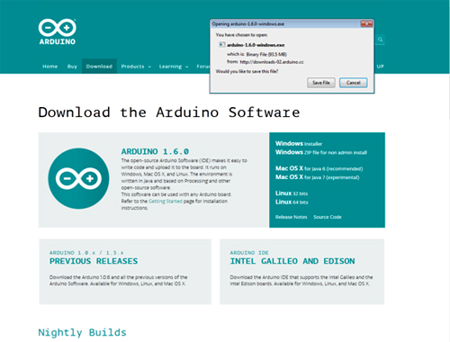
Figure2: Arduino Software website
The arduino folder contains example programs and also drivers that allow the arduino to be connected to your computer by a USB cable. Before we launch the Arduino software we have to be install USB drivers (Sometimes it will automatically installs the required driver software through online, in that case no need to install the drivers manually as we going to see in next few steps).
Plug one end of USB cable to Laptop/Desktop PC and the other end to the Arduino board. The power light (LED) on the board will glow and you may get a new message in your PC showing “Found New Hardware”. Ignore this message and cancel any attempts that windows makes to try install drivers automatically for you and try to install USB drivers manually through Device manager. Select my computer and right click on that and then select “Manage” it will open computer management pop up window as shown in figure3.
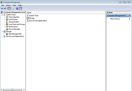
Figure3: Popup window
In this window select “Device Manager” in the list, under this select “Other Devices” shown in the list where you can see an icon “Unknown Device” with a yellow warning triangle on it as shown figure4.
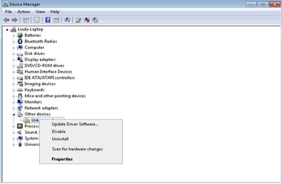
Figure4: Popup window
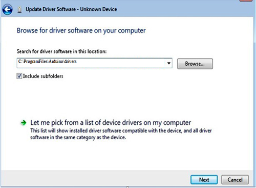
Right click on that and select the “Update Driver Software” then it will open up a pop up window shows to select either “Search Automatically for updated driver software” or “Browse for driver software on my computer”. Select the option to browse for driver software on my computer and navigate to the “C:\ProgramFiles\Arduino\drivers”.
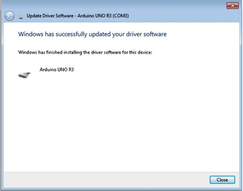
Click “Next” and if you get any security warnings, allow software to be installed. Once software installed successfully you will get a confirmation message that “Windows has successfully updated your driver software” and it will show the Arduino board name.
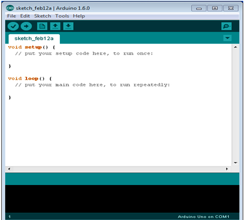
Now the Arduino software is ready and you can start by clicking “Arduino application”, this will start the Arduino IDE.
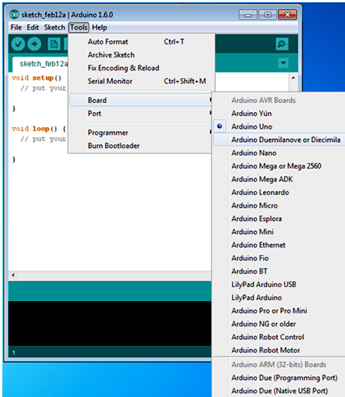
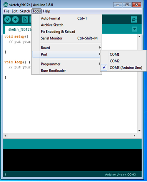
Before starting programming you have to tell the Arduino software which type of Arduino board you are using and the com port for which the Arduino board is connected.
From the “Tools” menu select the board that is “Arduino Uno”
From the “Tools” menu select the com port from “Serial port” option.
TWI: A4 or SDA pin and A5 or SCL pin. Support TWI communication using the Wire library.
There are a of other couple pins on the board:
AREF: Reference voltage for the analog inputs. Used with analogReference().
Reset: Bring this line LOW to reset the microcontroller. Typically used to add a reset button to shields which block the one on the board.
Communication:
The Arduino Uno has a number of facilities for communicating with a computer, another Arduino, or other microcontrollers. The ATmega328 provides UART TTL (5V) serial communication, which is available on digital pins 0 (RX) and 1 (TX). An ATmega16U2 on the board channels this serial communication over USB and appears as a virtual com port to software on the computer. The 16U2 firmware uses the standard USB COM drivers, and no external driver is needed. However, on Windows, a.inf file is required. The Arduino software includes a serial monitor which allows simple textual data to be sent to and from the Arduino board. The RX and TX LEDs on the board will flash when data is being transmitted via the USB-to-serial chip and USB connection to the computer (but not for serial communication on pins 0 and 1). A SoftwareSerial library allows for serial communication on any of the Uno's digital pins. The ATmega328 also supports I2C (TWI) and SPI communication. The Arduino software includes a Wire library to simplify use of the I2C bus. For SPI communication, use the SPI library.
Installing Arduino IDE for Windows:
The Arduino software (IDE) is available for windows, Linux and MAC operating systems. The installation process is different for all three platforms. In this lecture we are going work on how to install in windows PC, for other platforms they mentioned in the Arduino website how to install and use it. Get started by visiting the following website arduino.cc/en/Main/Software
Download the Arduino software for windows from the website as shown in the figure2, there is only one version of software for windows XP and windows7.
After downloading “arduino.1.6.0-windows.exe” file, by double clicking on the file will install the Arduino software and create a folder with name arduino in C folder.
Figure2: Arduino Software website
The arduino folder contains example programs and also drivers that allow the arduino to be connected to your computer by a USB cable. Before we launch the Arduino software we have to be install USB drivers (Sometimes it will automatically installs the required driver software through online, in that case no need to install the drivers manually as we going to see in next few steps).
Plug one end of USB cable to Laptop/Desktop PC and the other end to the Arduino board. The power light (LED) on the board will glow and you may get a new message in your PC showing “Found New Hardware”. Ignore this message and cancel any attempts that windows makes to try install drivers automatically for you and try to install USB drivers manually through Device manager. Select my computer and right click on that and then select “Manage” it will open computer management pop up window as shown in figure3.
Figure3: Popup window
In this window select “Device Manager” in the list, under this select “Other Devices” shown in the list where you can see an icon “Unknown Device” with a yellow warning triangle on it as shown figure4.
Figure4: Popup window
Right click on that and select the “Update Driver Software” then it will open up a pop up window shows to select either “Search Automatically for updated driver software” or “Browse for driver software on my computer”. Select the option to browse for driver software on my computer and navigate to the “C:\ProgramFiles\Arduino\drivers”.
Click “Next” and if you get any security warnings, allow software to be installed. Once software installed successfully you will get a confirmation message that “Windows has successfully updated your driver software” and it will show the Arduino board name.
Now the Arduino software is ready and you can start by clicking “Arduino application”, this will start the Arduino IDE.
Before starting programming you have to tell the Arduino software which type of Arduino board you are using and the com port for which the Arduino board is connected.
From the “Tools” menu select the board that is “Arduino Uno”
From the “Tools” menu select the com port from “Serial port” option.
Published date : 28 Feb 2015 11:23AM