

Sakshi Education

Arduino can sense the environment by receiving input from a variety of sensors and can affect its surroundings by controlling lights, motors, and other actuators. The microcontroller on the board is programmed using the Arduino programming language. In this article we will study how to interface temperature sensor to arduino and display the temperature value on the serial console as Celsius and Fahrenheit and at the same time based on the threshold value indicate the increase in the temperature through buzzer.
The components required for this project are
The components required for this project are
- Arduion Uno Board with USB cable
- Bread Board with jumpers cables
- LM35 Temperature sensor
- Buzzer
LM35 Temperature sensor:
The LM35 series are precision integrated circuit temperature sensors, whose output voltage is linearly proportional to the Celsius (Centigrade) temperature. The output voltage varies by 10mV in response to every oC rise/fall in ambient temperature that is linear +10.0 mV/ oC scale factor. The LM35 is rated to operate over a -55 ° to +150 °C temperature range. It operates from 4 to 20 volts. The LM35 Temperature sensor pin configuration details as shown in Figure1.
Figure1: LM35 Temperature sensor
Piezo Buzzer:
The piezo buzzer produces sound based on the reverse of the piezoelectric effect. The generation of pressure variation by the application of electric potential across a piezoelectric material is the underlying principle. These buzzers can be used to alert a user of an event corresponding to a switching action or sensor input. They are also used in alarm circuits. The buzzer produces a same noisy sound irrespective of the voltage variation applied to it. It consists of piezo crystals between two conductors. When a potential is applied across these crystals, they push on one conductor and pull on the other. This, push and force activity, brings about a sound wave.
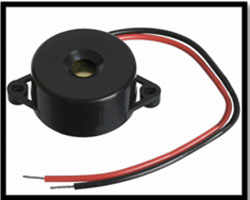
Figure2: Piezo Buzzer
The Red wire is connected to the Input and the Black wire is connected to Ground.
As we know that the Arduino Uno has 14 digital pins. We will write a code in order to measure the temperature using LM35 IC temperature sensor by reading the values of temperature by the AnalogRead keyword on the A1 pin of the Arduino Uno and display it on the serial console of Arduino. If the value of temperature is greater than 30 degree Celsius then the high signal is given to the Buzzer connected to the 12th pin of Arduino.
Setting up circuit:
- Connect ground pin (GND) from the Arduino board to the bottom row of the bread board with a jumper wire.
- Connect 5V pin from the Arduino board to the above the bottom row of the bread board with a jumper wire.
- Connect the pin14th from Arduino board to red wire of the buzzer via breadboard.
- Connect the black wire of the buzzer to ground on the breadboard.
- Connect the pin2 of LM35 sensor to Analog pin (A1) via breadboard.
- Connect the pin1 of LM35 sensor to Vcc (5V) on breadboard.
- Connect the pin3 of LM35 sensor to ground on the breadboard.
First we will write a code for the same in Arduino IDE platform, compile it and then flash the code into the Arduino.
Program:
void setup()
{
Serial.begin(9600);
pinMode(A1, INPUT);
pinMode(12, OUTPUT);
}
void loop()
{
int sensorValue = analogRead(A1);
int temperature = (sensorValue * 0.487);
Serial.print(temperature);
Serial.println("^c");
delay(2000);
if(temperature > 30)
{
digitalWrite(12,HIGH);
delay(2000);
digitalWrite(12,HIGH);
delay(2000);
}
}
Program Explanation:
- Void setup() :
This part of the program consists of the code which is executed only once. Like pin initialization etc.
- Serial.begin(9600);
Syntax: Serial.begin(baud rate)
This statement is used for setting the bits transmission between the PC and Arduino at an equal rate. Generally the Arduino operates at 9600 baud rate.
- pinMode(PINNUMBER , OUTPUT) / pinMode (PINNUMBER, INPUT);
Syntax: pinMode (pin number / variable name, INPUT/OUTPUT); pinMode is a keyword which initializes a pin which is specified by the pin number inside the parentheses and followed by the behavior of that pin i.e., whether that pin is acting as an Input or an Output Pin.
- Void loop() :
This part of the code is to be repeated continuously; hence it is included in the loop function.
int sensorvalue=analogRead(A0);
Here we define a variable “sensorvalue” whose value is the Analog input at the pin “A0”. This analog input is the value in millivolts.
- Serial.print(sensorvalue*0.4887);
This “Serial.print( statement) “ prints the statement or value pointed by the statement in the serial console.
Note: since we get the temperature sensor output in mill volts to convert it into degree Celsius we use the following formula:
Value in degree Celsius = value in mill volts * (500 / 1023).
- Serial.println:
This function is for new line.
Serial.println(“message”) prints the message and then goes to new line.
NOTE: Every statement must be terminated by a semicolon (; ).
- if ()
This is a conditional statement in which the statement in braces “{ } “is executed when the condition in if () is true, else the condition is false then the “else { }” is executed.
- Delay (2000):
Syntax: delay (time in milliseconds);
This statement helps us to put delays/ time gaps in milliseconds (ms).
So here delay (1000) gives a delay of 1000 ms which is equal to 1 second. Hence accordingly delays can be provided in the operations.
OUTPUT:
The below figure shows an LM35 temperature sensor and a piezo buzzer connected to Arduino Uno.
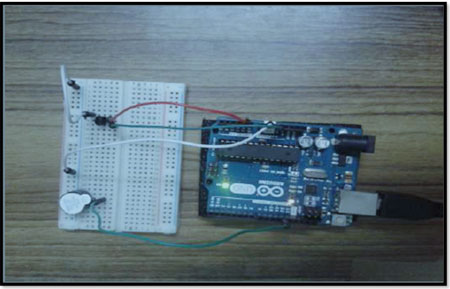
Fig.2 LM35 and piezo buzzer connected to Arduino Uno.
The output viewed at the serial console is shown below:
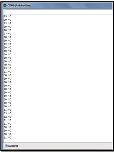
Fig.3 Temperature in degree Celsius output in Serial console Terminal.
Whenever the Temperature value goes above the 30 degrees centigrade it gives alert (beep signal) signal.
Published date : 21 May 2015 05:38PM