

Sakshi Education
By<br/>
D.BALAKRISHNA, Research Assistant, IIIT-H
By D.BALAKRISHNA, Research Assistant, IIIT-H The Arduino Uno can be programmed with the Arduino software IDE tool which is available for windows, Linux and Mac. The installation process is different for all the three platforms. If you have internet access then you can download the software from the link for all three platforms: arduino.cc/en/Main/Software
Windows installation:
The Arduino IDE tool is used to create new sketch, open an existing sketch and modify the sketch, verify/compiling the sketch and finally upload your sketch on to the Arduino Uno board from your computer.
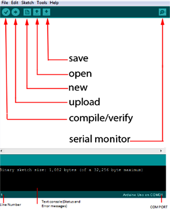
Buttons on the Arduino IDE toolbar from left to right and top to bottom:
Windows installation:
- Plug your board via USB and wait for windows to begin its driver installation process and after a few minutes the installation process will fail.
- Click the “Start Menu” and open “Control Panel”
- In the “Control Panel” navigate to “System and Security” then click on “System”. Once “System” window is up open then click on “Device manger”
- In “Device manger” window look under ports “Ports (COM & LPT)” you are able to see an open port named “Arduino Uno (COM XX)”, right clink on this port and select the “Update Driver Software” option.
- Next select the “Browse my computer for Driver software” option, then navigate to Arduino driver file named “ArduinoUno.inf” located in drivers folder of the Arduino Software download.
- Windows will finish up the driver installation.
- Double click on the Arduino application to open up.
- Select the board from tools. Go to “Tools” select “Board menu” under this select “Arduino Uno”
- Select the serial port from tools. Go to “Tools” select “Serial Port” “COMxx”
- Let’s open one example sketch and run. File ? Example ? 1.Basics ? Blink, This example blink the LED on the board continuously.
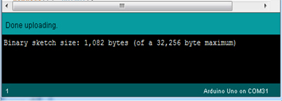
- Click upload button. After this at bottom you will get a message “Done uploading”
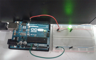
- Now you can see LED blinking once a second on the Arduino board.
The Arduino IDE tool is used to create new sketch, open an existing sketch and modify the sketch, verify/compiling the sketch and finally upload your sketch on to the Arduino Uno board from your computer.
Buttons on the Arduino IDE toolbar from left to right and top to bottom:
- Compile/Verify – Before your sketch can be upload to the board, your sketch need to check for compile time errors and then it needs to be converted into machine code that the board understands. This process is called compiling or verifying.
- Upload – This compiles the sketch and then transmits to the Arduino board if there are no compile time errors.
- New – This opens a new window to create a new sketch.
- Open – This loads a sketch from your computer.
- Save – This saves the changes to the sketch you are working on.
- Serial Monitor – This serial Monitor displays information passed from the Arduino Uno to the computer.
- Line Number – This shows what line number your cursor is on. It is useful since the compiler gives error messages with a line number.
- Text Console – This shows what the IDE is currently doing and is also shows error messages if you make any mistakes in typing your program.
- COMPORT – This shows for which port your Arduino board is connected.
Let us execute the basic ‘LedBlink’ example program to check that everything is functioning correctly.
Click on Arduino application go to à examples à Basics à Blink
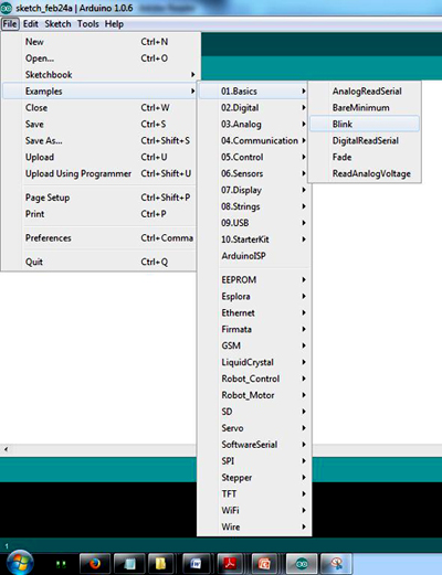
Figure 1: Opening Blinks example sketch
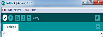
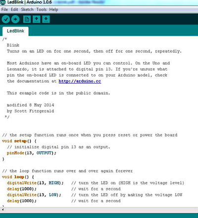
Blink example program
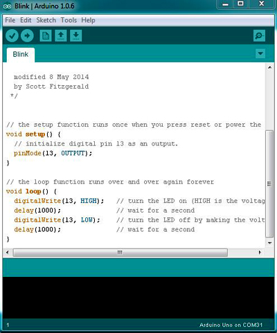
Figure2: Blink example code
The example sketches available with the Arduino IDE are read-only, that is you can upload them to an Arduino board but you cannot change them. If you want change this sketch, first thing you need to do is save as this sketch with your own name on your computer. From the file menu on the Arduino IDE, select the option “Save As” and then save the sketch as ‘LedBlink’.
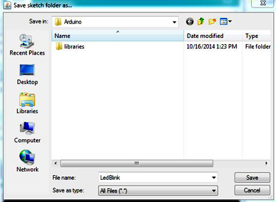
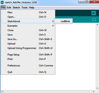
You have saved your “LedBlink” sketch in your sketchbook. Now you can open your sketch using File à Sketchbook menu option.
Now you can add any changes in the sketch and save the sketch and compile using ‘Verify button’ on the toolbar i.e. first button from the left on the toolbar.
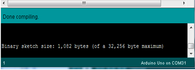
This will compile your sketch and give errors if any or successful done compiling; this converts your sketch into a format suitable for uploading to the Arduino board.
After successful compilation upload ‘LedBlink’ and sketch to Arduino board by using ‘upload button’ on IDE i.e. Second button from the left on the toolbar. At this point the some Led’s on the Arduino board should start blinking which shows that the sketch is transferring to the board.
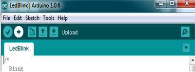
Finally the status will show “Done uploading”.
Once the uploading done, the Arduino board restarts and start blinking the Led at 13th pin on the Arduino board.
Let us see how the ‘LedBlink’ program works:
Comments: Comments are not actual part of program instructions, they are just comments about how the program works. These are useful for readability purpose, comments explains what the sketch is for.
Multiple line comment: It starts with ‘/*’ and continues until ‘*/’ is encountered.
Example: /* This is a multiple line comment */
Single line comment: It starts with ‘//’ and tells the computer ignore the rest of the line.
Example: // This is a single line comment
In Arduino programming each program must contain at least two functions.
Click on Arduino application go to à examples à Basics à Blink
Figure 1: Opening Blinks example sketch
Blink example program
Figure2: Blink example code
The example sketches available with the Arduino IDE are read-only, that is you can upload them to an Arduino board but you cannot change them. If you want change this sketch, first thing you need to do is save as this sketch with your own name on your computer. From the file menu on the Arduino IDE, select the option “Save As” and then save the sketch as ‘LedBlink’.
You have saved your “LedBlink” sketch in your sketchbook. Now you can open your sketch using File à Sketchbook menu option.
Now you can add any changes in the sketch and save the sketch and compile using ‘Verify button’ on the toolbar i.e. first button from the left on the toolbar.
This will compile your sketch and give errors if any or successful done compiling; this converts your sketch into a format suitable for uploading to the Arduino board.
After successful compilation upload ‘LedBlink’ and sketch to Arduino board by using ‘upload button’ on IDE i.e. Second button from the left on the toolbar. At this point the some Led’s on the Arduino board should start blinking which shows that the sketch is transferring to the board.
Finally the status will show “Done uploading”.
Once the uploading done, the Arduino board restarts and start blinking the Led at 13th pin on the Arduino board.
Let us see how the ‘LedBlink’ program works:
Comments: Comments are not actual part of program instructions, they are just comments about how the program works. These are useful for readability purpose, comments explains what the sketch is for.
Multiple line comment: It starts with ‘/*’ and continues until ‘*/’ is encountered.
Example: /* This is a multiple line comment */
Single line comment: It starts with ‘//’ and tells the computer ignore the rest of the line.
Example: // This is a single line comment
In Arduino programming each program must contain at least two functions.
- setup() à which is called once when the program starts.
- loop() à which is called repeatedly over and over again as long as the Arduino has power on or till the reset button is pressed.
Syntax:
void setup()
{
}
void loop()
{
}
Led Blink Program:
void setup()
{
pinMode(13, OUTPUT);
}
void loop()
{
digitalWrite(13, HIGH);
delay(1000);
digitalWrite(13, LOW);
delay(1000);
}
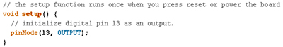
void setup()
This part of the program consists of the code which is executed only once. Like pin initialization, button initialization etc.
pinMode(13,OUTPUT)
Syntax : pinMode (pin number, INPUT/OUTPUT) ;
pinMode is a keyword which initializes a pin which is specified by the pin number inside the parentheses and followed by the behavior of that pin i.e., whether that pin is acting as an Input or an Output Pin. Here in this code 13th pin is initialized and that pin is acting as an Output pin.
void loop()
This part of the code is to be repeated continuously till Arduino powers off.
digitalWrite (13, HIGH)
Syntax: digitalWrite (pin number, LOW / HIGH);
This line is used to write / send a digital signal value i.e., either HIGH or LOW signal to the pin specified by the pin number. So 13 indicate Pin number to which a HIGH/LOW signal is sent.
delay(1000)
Syntax: delay (time in milliseconds);
This statement helps us to put delays/ time gaps in milliseconds (ms). So here delay (1000) gives a delay of 1000 ms which is equal to 1 second.
In the above program “pinMode(13, OUTPUT);” sets up the 13th pin as an OUTPUT pin.
Internally the LED is connected to 13th pin on the Arduino board.
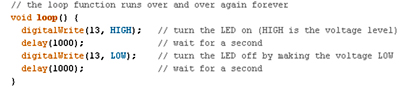
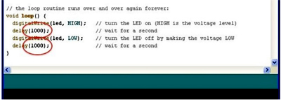
In the loop mentioned above the function “digitalWrite(13, HIGH);” writing HIGH out(HIGH means giving 5v out on the pin) on the pin 13 connected to LED which will turn the LED on, in The delay function “delay(1000);” which delays the number of milliseconds, in this 1000 milliseconds (1 second). In next line again we used digital write (“digitalWrite(13, HIGH);”) function for writing LOW (LOW means giving 0v out on the pin) out on the pin which turnoff the LED some duration based delay used delay function. This program will be executing until the Arduino board power is off.
Blinking Faster
You can blink LED faster by changing the parameter in ‘delay ()’ function. That is instead of 1000 milliseconds you can 2000 milliseconds so that the LED will blink faster.
void setup()
{
}
void loop()
{
}
Led Blink Program:
void setup()
{
pinMode(13, OUTPUT);
}
void loop()
{
digitalWrite(13, HIGH);
delay(1000);
digitalWrite(13, LOW);
delay(1000);
}
void setup()
This part of the program consists of the code which is executed only once. Like pin initialization, button initialization etc.
pinMode(13,OUTPUT)
Syntax : pinMode (pin number, INPUT/OUTPUT) ;
pinMode is a keyword which initializes a pin which is specified by the pin number inside the parentheses and followed by the behavior of that pin i.e., whether that pin is acting as an Input or an Output Pin. Here in this code 13th pin is initialized and that pin is acting as an Output pin.
void loop()
This part of the code is to be repeated continuously till Arduino powers off.
digitalWrite (13, HIGH)
Syntax: digitalWrite (pin number, LOW / HIGH);
This line is used to write / send a digital signal value i.e., either HIGH or LOW signal to the pin specified by the pin number. So 13 indicate Pin number to which a HIGH/LOW signal is sent.
delay(1000)
Syntax: delay (time in milliseconds);
This statement helps us to put delays/ time gaps in milliseconds (ms). So here delay (1000) gives a delay of 1000 ms which is equal to 1 second.
In the above program “pinMode(13, OUTPUT);” sets up the 13th pin as an OUTPUT pin.
Internally the LED is connected to 13th pin on the Arduino board.
In the loop mentioned above the function “digitalWrite(13, HIGH);” writing HIGH out(HIGH means giving 5v out on the pin) on the pin 13 connected to LED which will turn the LED on, in The delay function “delay(1000);” which delays the number of milliseconds, in this 1000 milliseconds (1 second). In next line again we used digital write (“digitalWrite(13, HIGH);”) function for writing LOW (LOW means giving 0v out on the pin) out on the pin which turnoff the LED some duration based delay used delay function. This program will be executing until the Arduino board power is off.
Blinking Faster
You can blink LED faster by changing the parameter in ‘delay ()’ function. That is instead of 1000 milliseconds you can 2000 milliseconds so that the LED will blink faster.
Published date : 10 Mar 2015 05:32PM