

- Controlling brightness of LED based on potentiometer.
- Interfacing Buzzer to Arduino to get Voice alarms.
The learning from this project is how to interface potentiometer to the Arduino.
The components required for this project are
- Arduion Uno Board with USB cable
- Bread Board with jumpers cables
- LED
- 470 ohm resistor
- Potentiometer
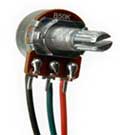
Potentiometer:
A potentiometer is also known as a variable resistor. When supply with 5V, the middle pin outputs a voltage between 0V and 5V, depending on the position of the knob on the potentiometer. A potentiometer is a perfect demonstration of a variable voltage divider circuit. The voltage is divided proportionate to the resistance between the middle pin and the ground pin. In this Experiment, we will learn how to use a potentiometer to control the brightness of an LED.
Figure1: Potentiometer
LED: A Light emitting diode is a two lead semiconductor light source. LED’s are mostly used as indicator source for electronic devices. LED’s require a less power to light up by comparison and they are more energy efficient.
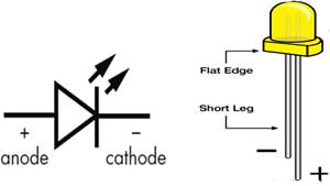
Figure2: LED Symbol with polarity
The polarity of LED indicates that the positive side of led is called ‘anode’ and is marked by having a longer leg. The other side indicated that the negative side of led is called ‘cathode’ is marked by having shorter leg as shown in the figure.
Setting up circuit:
- Connect ground pin (GND) from the Arduino board to the bottom row of the bread board with a jumper wire.
- Connect 5V pin from the Arduino board to the above the bottom row of the bread board with a jumper wire.
- Connect the pin12th from Arduino board to long leg of the led via breadboard.
- Connect the short leg of the led to one end of resistor via breadboard.
- Connect the other end of resistor to the ground column on breadboard.
- Connect the center pin of potentiometer to A0 pin of Arduino via bread board.
- Connect the one end pin of potentiometer to ground column on bread board.
- Connect the other end pin of potentiometer to 5V pin column on bread board.
First we will write a code for the same in Arduino IDE platform, compile it and then flash the code into the Arduino.
Program:
int potpin = A0;
int ledpin = 12;
void setup() {
// put your setup code here, to run once:
pinMode(ledpin, OUTPUT);
}
void loop() {
int sensorvalue;
sensorvalue = analogRead(potpin);
digitalWrite(ledpin, HIGH);
delay(sensorvalue);
digitalWrite(ledpin, LOW);
delay(sensorvalue);
}
Program Explanation:
- int ledPin = 12
Here we are defining a variable by name “ledPin” which is assigned a pin number 12. So use of this variable anywhere in the program will mean use of the 12th pin for operations.
- int potpin = A0;
Here we are defining a variable by name “potpin” which is assigned a pin number A0. So use of this variable anywhere in the program will mean use of the A0 pin for operations.
- Void setup()
This part of the program consists of the code which is executed only once for pin initialization, button initialization etc.
- pinMode(ledPin , OUTPUT)
Syntax: pinMode (pin number / variable name, INPUT/OUTPUT);
pinMode is a keyword which initializes a pin which is specified by the pin number inside the parentheses and followed by the behavior of that pin i.e., whether that pin is acting as an Input or an Output Pin. Here in this code “ledPin” indicates pin number 12 which is to be initialized and that pin is acting as an Output pin.
- Void loop()
This part of the code is to be repeated continuously; hence it is included in the loop function.
- analogRead(potpin)
The Arduino can read external voltages on the analog input pins using a built-in function called analogRead().
- digitalWrite(ledpin , HIGH)
Syntax: digitalWrite ( pin number / variable name , LOW / HIGH);
This line is used to write / send a digital signal value i.e., either low or high signal to the pin specified by the pin number. So ledPin indicates Pin number 12 to which a high signal is sent and in other line a low is sent.
Syntax: delay (time in milliseconds);
This statement helps us to put delays/ time gaps in milliseconds (ms). So here delay (1000) gives a delay of 1000 ms which is equal to 1 second. Hence accordingly delays can be provided in the operations.
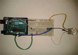
Figure3: Potentiometer with Arduino
Interfacing Piezo Buzzer to Arduino to get Voice alarms
The learning from this project is how to interface a Peizo buzzer to the Arduino
Piezo Buzzer:
The piezo buzzer produces sound based on reverse of the piezoelectric effect. The generation of pressure variation by the application of electric potential across a piezoelectric material is the underlying principle. These buzzers can be used alert a user of an event corresponding to a switching action or sensor input. They are also used in alarm circuits. The buzzer produces a same noisy sound irrespective of the voltage variation applied to it. It consists of piezo crystals between two conductors. When a potential is applied across these crystals, they push on one conductor and pull on the other. This, push and force activity, brings about a sound wave.
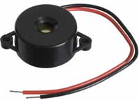
Figure4: Piezo Buzzer
The Red wire is connected to the Input and the Black wire is connected to Ground.
The components required for this project are:
- Arduion Uno Board with USB cable
- Bread Board with jumpers wires
- Piezo Buzzer
- Connect the positive pin (Red wire) to Arduino digital pin 9
- Connect the negative pin (Black wire) to Arduino ground pin (GND).
Program:
void setup()
{
pinMode(9, OUTPUT); // sets the pin as output
}
void loop()
{
analogWrite(9, 128); //any value can be used except 0 and 255
delay(500); //wait for a delay in ms
analogWrite(9, 0); //0 turns it off
delay(500); //wait for a delay in ms
}
Program Explanation:
- Void setup()
This part of the program consists of the code which is executed only once when the program starts.
- pinMode(9 , OUTPUT);
Syntax: pinMode (pin number / variable name, INPUT/OUTPUT);
pinMode is a keyword which initializes a pin which is specified by the pin number inside the parentheses and followed by the behavior of that pin i.e., whether that pin is acting as an Input or an Output Pin.
- Void loop (): This part of the code is to be repeated continuously until Arduino board powers off.
- analogWrite (9 , value) :
Syntax: analogWrite (pin number / variable name, value);
This line is used to write / send a analog value to the pin specified by the pin number.
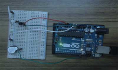
Figure5: Piezo Buzzer with Arduino